BrianW
-
Posts
64 -
Joined
-
Last visited
Content Type
Profiles
Forums
Blogs
Gallery
Downloads
Events
Store
Everything posted by BrianW
-
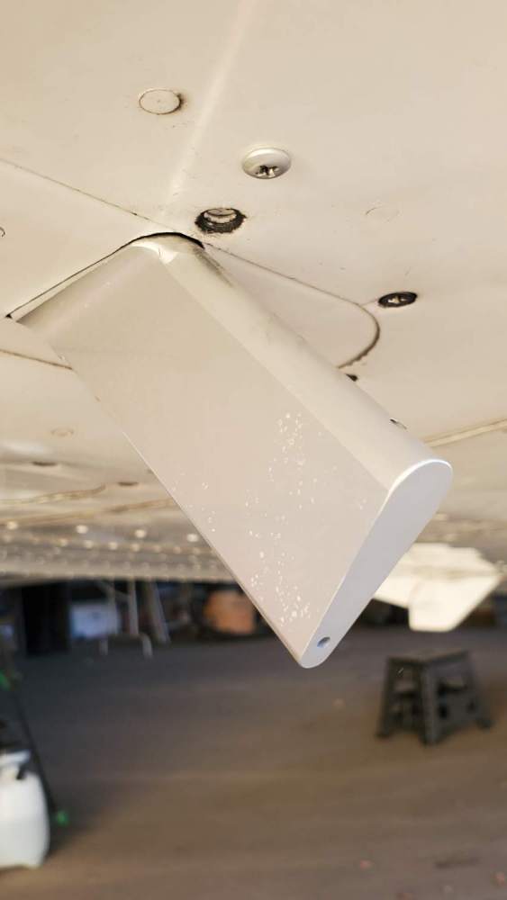
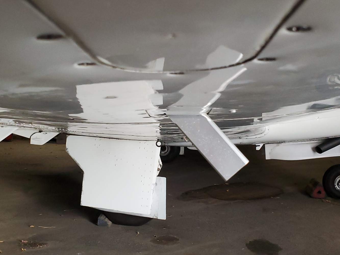
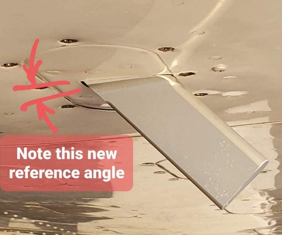
 After talking with Bendix Technical support, I was told Bendix stopped selling the KLR10 in 2013/2014. Bendix had limited technical information but said the KLR10 was actually produced by Alpha Systems for Bendix. They gave me Alpha System's phone number. I went over to Alpha System's website. Our KLR10 is equivalent to their "Eagle" kit. They had much better documentation for installation and calibration. I spoke with (I think it was Mark) at Alpha Systems. He explained the operation and calibration procedure. He said the probe angle moves at 5 degree increments. He called this the "coarse adjustment". The calibration button sets the "fine adjustment". He said that based on the OAA showing the blue circle and yellow bar below (when it said "invalid set point") meant the probe was angled down too much, and that the probe tip needed to be rotated up 5 degrees to the next locking point, and reattempt the calibration again. I'm glad I spoke to Alpha Systems for clarification. In order to rotate the probe tip up, I had to increase the hole size that the probe goes through on my wing inspection panel at the front. I had to Dremel out about 1/8" material from the access cover at the front of the probe and rotate the probe up. (see photos). I flew the plane and it calibrated easily at the 1.3 Vs for OAA calibration. By the way, the choice for the probe location was in the right wing access panel. There was nothing behind this access cover that requires the removal of this access cover for the regular annual inspection. The only thing I would have changed would be to cut the probe hole NOT in the center of the cover plate. I would move the probe 1" left or right of center. At center, the front center screw gets blocked by the probe (see my photo) and will not allow the use of the center screw. Also, I'd shift the inside probe mounting flange as rearward as possible so when you remove that little bit of material in front of the probe (to allow the probe to be rotate up a bit more) the probe hole would not be so close to the front of the access cover hole (you can see its close in the photo). I'd prefer the front/back placement of the probe hole to look more centered in the cover plate. This AoA works great now. I'm happy with my AoA now. But Bendix no longer sells and supports the KLR10. Alpha Systems have continued to get better and have great upgrades, accessories, and support. If you want an AoA, I'd definitely choose an Alpha Systems unit.


-
Hi Mark I've attempted calibration about 4 times unsuccessfully and then 2 more times where I was able to get the OAA to accept. The OAA is the tricky part of the calibration. The still-air in hanger calibration and the cruise calibration don't pose the problem. In order to set the OAA I calculated my v speeds based on the plane's flight weight rather than the gross weight Vs in the POH. So instead of Vs being 72mph, I calculated my Vs to be 67mph. Then 1.3Vs=87mph. But when I tried set OAA calibration at 87mph I kept getting "invalid set point". So I slowed more and tried again and again. It wasn't until I was at 80mph that the unit announced calibration set. I completed the cruise calibration and landed. I didn't like that calibration and researched some more and checked my calculations. I went thru the calibration again yesterday, and again I had to be at 80mph or less for the unit to accept OAA. That is only 1.15Vs! With the calibration complete, when I approached on final, it displayed cruise. And as I was rolling down the runway it finally announced "watch AOA", then "too slow". That's no use! I will call Alpha Systems for some tech support. I think they make the KLR10 for Bendix. Unfortunately in my calls to Bendix tech support, they seem to have no technical expertise and are unfamiliar with their KLR10.
-
Hi Mark I've attempted calibration about 4 times unsuccessfully and then 2 more times where I was able to get the OAA to accept. The OAA is the tricky part of the calibration. The still-air in hanger calibration and the cruise calibration don't pose the problem. In order to set the OAA I calculated my v speeds with the based on the planes flight weight vs the gross weight. So instead of Vs being 72mph, I calculated my Vs to be 67mph. Then 1.3Vs=87mph. But when I tried set OAA calibration at 87mph I kept getting "invalid set point". So I slowed more and tried again and again. It wasn't until I was at 80mph that the unit announced calibration set. I completed the cruise calibration and landed. I didn't like that calibration and researched some more and checked my calculations. I went thru the calibration again yesterday and again I had the be at 80mph or less for the unit to accept OAA. That is only 1.15Vs! With it calibrated upon final it displayed cruise. And as I was rolling down the runway it finally announced "watch AOA", then "too slow". That's no use! I will call Alpha Systems for some tech support. I think they make the KLR10 for Bendix. Unfortunately in my calls to Bendix tech support, they seem to have no technical expertise and are unfamiliar with their KLR10.
-
Well, I've done 3 flights trying to get a calibration set with no success. I calculated the 1.3Vs as shown in the Installation Instructions. My landing manifold setting is 13". I fly the 13" straight and level using the trim and slowed down to 1.3Vs (88 mph in my case). And I kept getting the "invalid set point error". About a year ago, I incorrectly set the calibration using Vso. But the indications were nonsense. As such, the KLR10 gave no indication until I was landed and slowing. As I would turn off to a taxiway the AoA would finally announce "pull up too slow". Yup, using Vso configuration was wrong for calibration. But the instructions said to configure it as you would for landing. I guess they meant say "Fly at 1.3Vs. Set the throttle and prop as you would for landing, and trim back to attain 1.3Vs in straight and level flight". Since I was able to calibrate to Vso in the past, if I was able to get it to at least set calibration (albeit at the Vso), then I'd know the KLR10 was still able to calibrate. This would lead me to believe the KLR10 was working, but I'd have to change the probe angle. If it couldn't calibrate, then I'd suspect something else was wrong to prevent calibration. BTW, changing the probe angle requires cutting the metal on the wing surface that the probe passes thru. And I didn't want to do cutting until I was absolutely sure. Since I couldn't calibrate in the clean configuration at 1.3Vs, I tried to calibrate in the dirty configuration at 1.3Vso (flaps down, cowl flaps open, and landing gear extended). The KLR10 couldn't calibrate at 1.3Vso either (despite being able to calibrate to 1.3Vso one time in the past). So my Bendix KLR10 is either no longer working or I need to redo the still air calibration in the hanger. This is a royal pain. The Bendix Instructions are not 100% clear, Bendix tech support seems unfamiliar with installation or troubleshooting their product, and no-one on any forums seems to have posted any useful pictures or write-up of their installation. It feels that I am trying to deduce troubleshooting and figure out the installation by myself. I'd expect this lack of information and trouble for a new or prototype product. But the Bendix KLR10 has been out for years, and hundreds of these have been installed.
-
Hi All, During my last annual I had the Bendix KLR10 installed in my M20J. Lots of decisions regarding locating the probe to a good location and the indicator to a good location. They left the in-flight calibration to me, but the KLR10 is giving me the "invalid set point" error when I try to set the OAA (Optimum Alpha Angle). I had the probe mounted in an inspection panel location. It is 12 inched back of the leading edge. And the chord indicator on the probe appears parallel to the chord of the wing (see photos). I contacted Bendix customer support but they seemed like they had no knowledge with the Installation/calibration. Has anyone here on Mooneyspace installed the KLR10 in their Mooney? I'd like to find out what angle you installed your probe at? Mine is still set at the default 50 degrees (see photo). The Installation Instructions say when I get the "invalid set point" error during OAA calibration to reduce the probe angle in 5 degree increments. And to cut the opening for the probe larger. I don't want to make a mistake and do this multiple times. Once I cut a larger hole thru my inspection panel, for a reduced probe angle, I can't put the material back. What angle is your probe at? Any help or photos would be appreciated. Thanks BrianW

-
Hi All, I'm looking for the manual that comes with the Inogen Aviator G5-1265. I can find both the technical and user manuals for the medical G5. But the G5 Aviator manuals cannot be found. If the Inogen G5 Aviator was tested to 18000 feet, wouldn't there be some record of this unit (manuals or tests) at the FAA website like other PMA parts and devices? Thanks, Brian
-
Test
-
Hmmm...I added it to my signature and saved it. I'll have to try again later.
-
Yeah, your right, no map. Hmmmm... Let me dig for my signature. Ok, now let's see if it works... Brian
-
I went to LASAR and found the rigid step for $1032, but it didn't have the streamlined tubing that I've seen on the other Mooneys (it just is a round down tube).
-
Cool !!! Thanks guys! The map has been added to my signature!
-
Hi, I am looking for a rigid fixed step for my 1979 Mooney M20J . My short wife has some trouble stepping all the way up on the wing to get in, or jumping down to get out! I tried searching the internet, but all I found were retractable ones on eBay. But I'm not interested in retractable. I want the newer rigid entry step. It would be easier to search it if I knew the actual Mooney part name or even the part number. It would be nice to find the engineering drawing of it, to make an owner produced part, if I cannot find a used one for sale. Any help would be greatly appreciated. Thanks, Brian
-
Hi All, I did a search here and don't know how to add the US Map with the states that I've visited to the area at the bottom of my posts like I've seen on other MS'ers. So, 1) Where do I find a map that can be filled in? 2) Is it easy enough to fill in states visited and update the map? 3) In the forum posts, what is the bottom portion of our posts called? (I may have been able to figure it out, but I was guessing the name for my searches - footer, signature, tagline...grrrr!) 4) How do I add the map to the bottom section of my posts (whatever that bottom portion is called)? Thanks, Brian
-
The POH doesn't specify the value where the tach time runs at the same speed as real time. According to Mooney Technical Support, over the years numerous tach manufacturers/supliers were used. Some tachs were mechanical, and some were electronic. But Tech Support can look up the specs for the original tach installed in your plane by the tach's part number and your plane's serial number. Given the wide variety of tachs, and the POH not having the spec where tach equals real time, it seems prudent to have a default valve but allow the installer or pilot to fine tune settings. And 10 hours until it locks the installer/user out from making changes later is probably an FAA requirement to prevent time tampering. So after 10 hours one has to send it back to JPI to modify. JPI has a lot more settings than just those covering the basis specs given in the POH, like MAP calibration, date, time, gps type, etc. And those should be fine tuned and set during install or shortly thereafter. I'm not sure how it looks when JPI locks out certain features after 10 hours. It may allow you to still get to the variable but not allow any changes to be saved. Or it may hide the setting entirely in it's menu system. I'm not sure. If it allow you to see the rpm adjustment but not save any changes that may explain why someone's tach may be running faster on the JPI over the stock mechanical tach, cuz the mech tach may run true at 2500 while the JPI may not allow a change from it's default of 2400rpm, if it been installed for over over 10 hours. I would call Mooney Tech Support to get your true rpm (don't just enter random numbers hoping to see some effect). Get you real number and only use that number! After I had my true rpm number for my plane, I'd definitely call JPI to figure out why there's a discrepancy.
-
Hi All, I was looking for definitive info and couldn't find it easily, so I researched it and made a call to Mooney International Technical Support. The JPI EDM 900 has its tach adjustment factory default to be 2400 rpm. But I wasn't sure what Mooney set our average cruise engine speed to be on our tachs for our tach time. I called Mooney International Technical Support regarding my M20J. They looked up my original mechanical tach and told me it was setup for tach time to equal run time at 2500rpm. Its a good idea to change both the tach time and tach adjustment before the JPI EDM900 runs past its first 10 hours. After 10 hours the tach settings lock and cannot also be changed. This is to prevent tampering. After it is used more than 10 hours (or if you buy someone else's used JPI), you must send it back to JPI to have the tach settings modified. I'd set the tach time to your TTAF, which makes for easy logbook entries. It's important to set your tach adjustment to match what Mooney specified. Otherwise if you don't, and it remains at 2400rpm, when you cruise at 2500rpm your tach will be adding time faster than clock time accidentally "aging" your plane adding hours at a faster rate than it was supposed to.
-
Here's the completed glareshield!

-
I downloaded the Mooney M20J manual and it indicates for satisfactory operation of the Attitude Indicator and Directional Gyro that the satisfactory vacuum operating range is 4.00 inHg to 5.70 inHg. However the HI/LO VAC malfunction indicator light on the annunciator illuminates when outside the range of 4.25 to 5.50 inHg. The light blinks-on when below 4.25 inHg and is solid-on when above 5.50 inHg. The manual says that when the light flashes or is on solid, the gyros (for AI and DG) should not be considered reliable. My M20J is in for its annual and some work was done on my instruments. My mechanic says the annunciator HI/LO VAC light wont turn off and recommends an actual suction gauge for improved reliability and better diagnostics. I don't mind the better information provided by an actual gauge. I still like the idea of the dummy light flashing when there is a malfunction to help get my attention and alert me. I'm just writing this info down as a response to provide empirical numbers and make it easier for myself and others to figure out what is normal in the future.
-
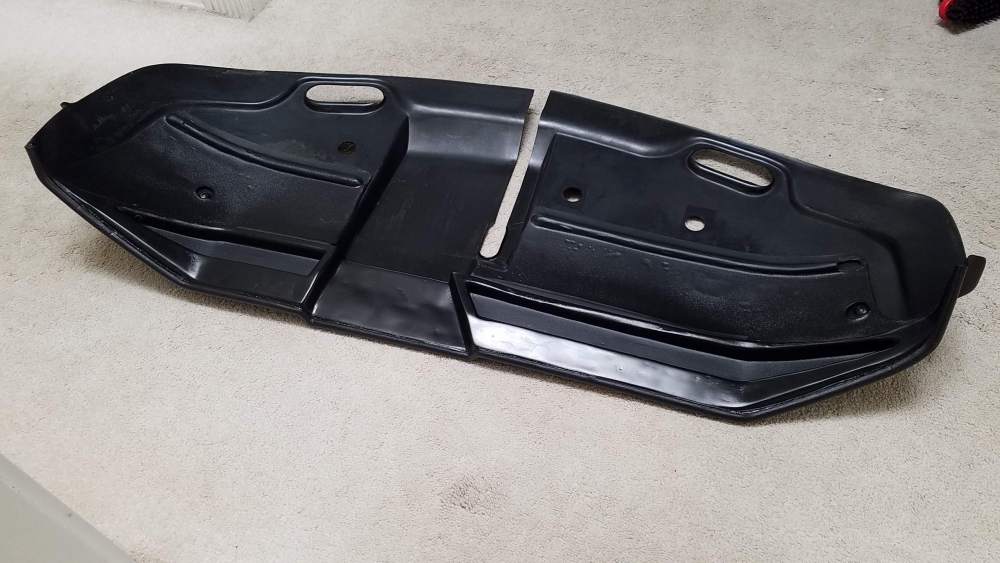
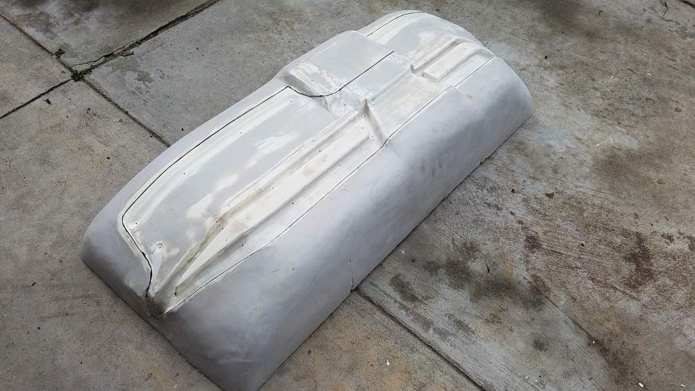
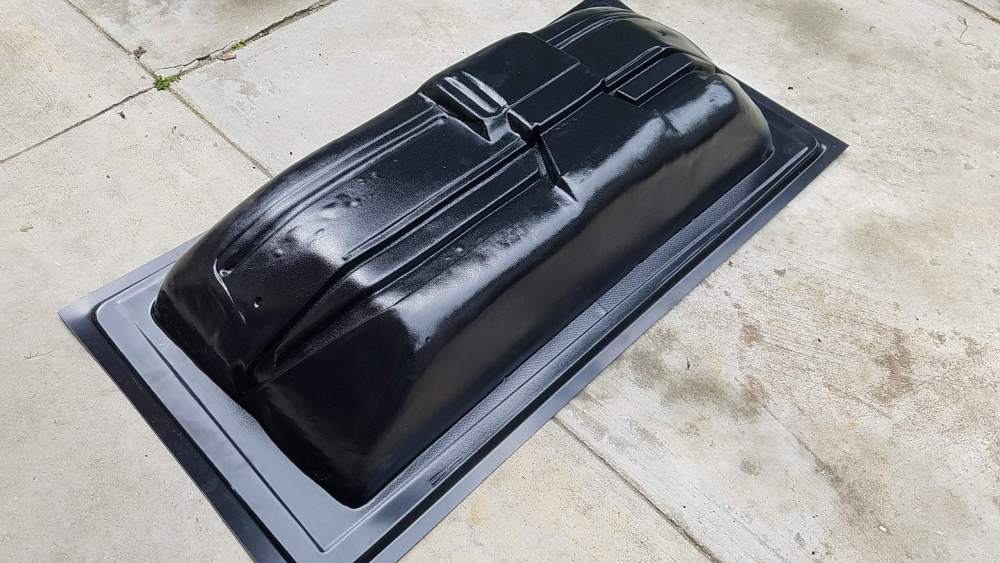
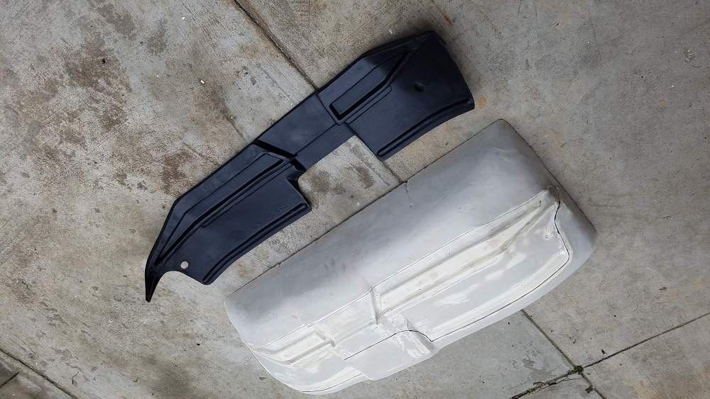
I believe the vac formers heated the abs too fast causing the bubbles, non-uniform heating, and poor surface finish. The high heat also blistered and bubbled my mold. I can do bodywork to repair the mold, but later for that! At least I got a part that's good enough. Since it's the underside of the glareshield,100% cosmetically perfect isn't necessary. I was able the smooth out some of the bigger bubbles with a heatgun and wooden blocks. Today I was test fitting the upper and lower glareshield in my Mooney. I did the adjusting with the heatgun again, and trimming with dremel. It lays flat, follows the panel and windshield contours, and looks quite acceptable. I'll bond the upper and lower parts together using the same oem methods. I can't wait until it's done, and get all my sign-offs, so I can fly the plane again.
-
Here are the photos of the mold, the vac formed part and the part trimmed:
-
UPDATE - I took the mold into the vacuum mold shop. They said it looked very good for a first timer. They pulled the form with .090" thick Royalite. It wasn't perfect, a few small spots that look like air got trapped underneath and one area where it had a deep draw and the material was stretched thin. They then offered to pull a second part with .125" Royalite to have more material for the deeply drawn section. The second one wasn't better. It appeared that my form had some air bubbles in my plastic form itself. The trapped air within my mold forced up air bubbles that then permanently set when it cooled. They said that if I body-shop my mold (sanding and filling) to restore the smooth contours, I could use fiberglass to make a negative and more durable mold. They said negative molds produce better surface finish results. I may do that. Meanwhile, my first vacuum formed part is 100% structurally sound and looks pretty darned nice. I will attempt to gently heat and smooth out the wavy area to see if it can look perfect. I think it will still turn out nice.
-
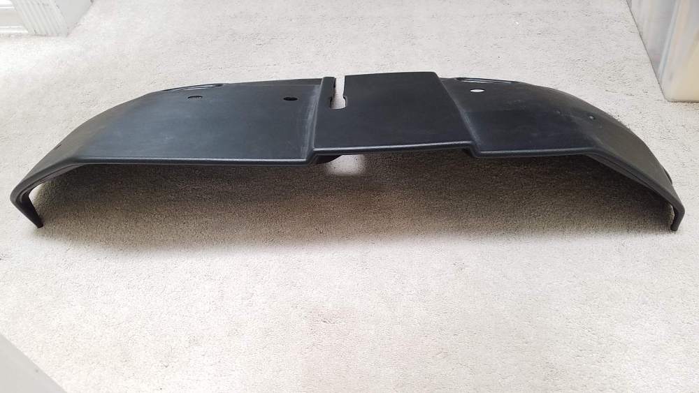
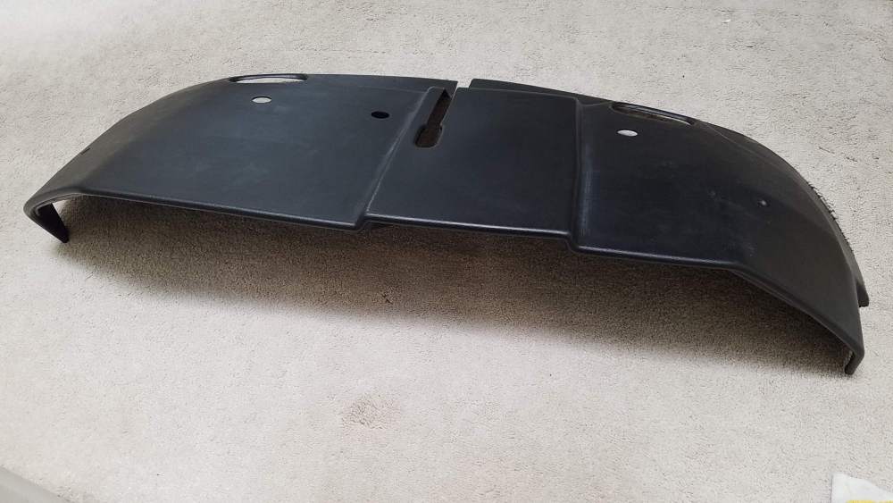
An update on the project so far: I'm almost complete on the mold for the lower section of the glareshield (a.k.a. the light tray p.n. 130342-007). Just need to drill holes through it for the vacuum form table. I called Mooney Technical Support in Texas to ask about the material used in the M20J glareshields. Mooney called me back and read the information off the drawing. He told me the material was ABS plastic. He said the ABS material name on the drawing calls it Royalite 26 Series, HC grain, black. He said the ABS plastic makes it very easy for customers to repair their own glareshields by gluing or melting together the ABS. (He mentioned that in later Mooney production they moved to making the glareshields out of fiberglass). I previously bought what I thought was a new and complete glareshield. But when it arrived, it was incomplete and useless without the missing mating parts. Turned out it was just the upper glareshield section, pn 130342-003 (again not useable without the missing mating parts). The lower section that I am going to vacuum form is the crucial missing part. If time weren't a consideration I'd love to make a mold of the upper section as well before I bond the 2 parts together (just in case the upper warps or cracks in the future). But that would take even more time, and I really want to get my glareshield put together so I can get my plane out of the shop.
-
Garmin or Aspen EFIS options to work with Century Autopilot
BrianW replied to BrianW's topic in Modern Mooney Discussion
My hair almost stood up on the back of my neck with you creeping on databases searching for me. Be that as it may, I see what you are seeing. I accidentally inverted my number when I signed onto Mooneyspace. I'm N3755H and posted a pic of my plane for my avatar -
Garmin or Aspen EFIS options to work with Century Autopilot
BrianW replied to BrianW's topic in Modern Mooney Discussion
Hi Jim, That's strange, my N3755H tail number doesn't appear in my avatar. It's not custom. It's just the plane's number as I bought it. Does it has some meaning to you? Thanks, Brian -
I am planning on making the underside section. It'll take me several hours to make the mold pattern. The part can be then vacuum formed for $45 setup and $40 for the abs sheet.
-
Hi Art, No, I didn't see that post before. I took a look at it. Lots of cool stuff there. But, the glareshield is the old style where it goes straight across the panel. Mine has the hump in the middle area where my center post goes thru (as shown in my photos). I committed to using the glareshield from Aerocomfort. I spent a couple hours today peeling back the leather from the edge and trimming the glareshield to fit in my 1979 M20J. It is because the new glareshield with the leather covering looks so good that I am commiting to using it, even though I will need to mold the underside section for stiffening and lights. I'll post pictures soon. Thanks.