

Jer
-
Posts
33 -
Joined
-
Last visited
Content Type
Profiles
Forums
Blogs
Gallery
Downloads
Events
Store
Everything posted by Jer
-
Replying to RagsfF15E No I did not locate another switch. I am not sure what it is. I have the S/N correct service and parts manual and I can't figure out what it really is. If it is one with a standard microswitch, I would just change that out, assuming I was smart enough to figure out the removal process. I'll cross that bridge if need be. I did however buy an extra sonalert in case the project pointed that way. Not here yet. amazon $35, 3 or 4 day delivery. I guess it will just be one more piece of hardware for my son to throw out after I'm gone. Please pardon the cynicism. Jer
-
Folks: Here is the report on today's effort. I went out with the intent to complete the circuit by taping the switch vane in place up. Then turning master on and testing voltage at various points on the circuit, to see if there was a large voltage drop across the switch, indicating excess resistance. You can understand my disappointment when I turned on the master and the sonalert sounded. I only did two voltage tests. Checked 22,7 volts to ground on the plus side of the sonalert and 22.7 acrosss the sonalert. I de-taped the vane, and hand triggered it a number of times to get it to fail, but it did not. I reinstalled the sonalert into a little panel that held two other sonalerts, screwed it up, put on the fabric cover. I kept running out to the vane switch each step of the way, expecting a failure and not wishing to discover that when fully assembled. So now it works. Very un-satisfying solution to this. I went and test flew it into a stall, and it didn't give me but 3 or 4 kts warning prior to stall (clean), but I'm going to let that dog lie. Regarding all the advice and help you have all offered, thank you very much. You have been very supportive. Regarding the advice from PT20J and M201MKTurbo. those issues are somewhat moot now, but lacking any advice at the time, several days ago, somewhat of a Hail Mary, I sprayed some contact cleaner into around the vane from the leading edge and by feel only, tried to spray the switch up through the access hole reaching in as deep as I could. Well, what's done is done on that score. I was intending to finish this note with, "Last call, leaving the pattern", but without a clear cause and corrective action, I am likely to be back. Thanks all, stay safe. Jer
-
Today's investigation led to some perplexing results. Removed the Sonalert, and put it across a 28v APU. Sounded fine. I removed the negative lead (which connects to the stall vane switch and then to ground), and checked that lead for continuity with the airframe ground while the vane was triggered. Checked zero OHMs, as one would expect. However, connecting this back to the sonalert negative, did not sound the alarm. However, just connecting a wire shunt between the negative terminal on the sonalert and the airframe, and the thing does sound. The conclusion of my electrical engineer tie-down neighbor was that while the negative side of the circuit, did show continuity to ground, there must be excessive resistance in that portion of the circuit. Tomorrow I intend to wire it up correctly, turn on the master, trigger the vane, and check the voltage drop across the sonalert. I believe I did this earlier but did not recognize the importance of this test. I believe the plus side checked 24 v to ground and the negative side checked 16v to ground. I did not directly check voltage across the unit, but if what I think I recall is true, there would be 8 volt drop across the device, with the other 16 volt drop eaten up by excessive resistance in the negative side of the circuit. If this is so, I will check quite locally for a voltage drop across the stall vane switch. It may have continuity, but also excessive resistance, in which case I will have the opportunity to try laparascopic removal of the switch from that access panel. Thanks for all your help. Jer
-
dkkim: Thanks for the sylvan metaphor. I don't suspect the wire as where I tested at the end of the line, I had voltage, and when grounding that out, juice was flowing in the circuit. If the wiring shorted out between the battery and the sounding device, the breaker would have tripped. If the wire shorted out after the sound device and the stall vane switch, I wouldn't have voltage at the switch, which I did. I have great hope for the noisemaker being the issue. If that fails to be the issue, I think the next logical step would be to check my hearing, which unfortunately would then open the door to medical metaphors. Jer
-
Thank you. I'll try an find it and test it. Does anyone have any comment on hearing the stall warning through headphones. I don't really recall that myself.
-
What is a sonalert, and where is it?
-
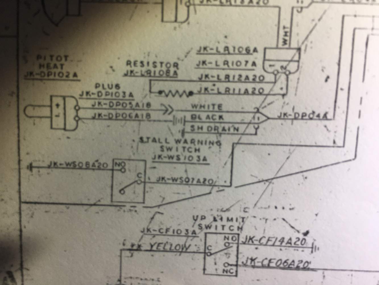
Folks: I appreciate all the help, particularly the detailed instructions of Will; however, I have been barking up the wrong tree. I haven't even found the correct tree yet. I looked up the schematic last night, and realized if the "hot" wire coming in to the switch was grounded out (bypassing the switch of unknown reliability), the horn should sound, I took a voltmeter to that wire (showed 23 volts), grounded it out and no horn. As long as I was doing the exploratory surgery, I took an ohm meter and checked the function of the switch, which showed proper functioning. I closed and stitched up the patient's wound. Meanwhile, my tie-down neighbor, a fellow Mooney driver dropped by and I disclosed my suspicion the the actual horn may be the issue. He said he hears the warning in his headphones, so if so, the lack of audible horn really wouldn't be a problem if it played in my headphones. I turned master and radio switches on, put on the headphones and triggered the stall vane. Just silence. Anyone want to point me where to go next? Please pardon my mixing sylvan and medical metaphors. Jer
-
Thank you rich, the painted in place is something I did not consider. With regards to checking out through the access plate, it is about 14 inches back from the leading edge, as evidenced by 14 inches of cuts on my forearm as measured from my fingertips. I tried looked at it through fiber optic bore scope and holding i phone in hand, with little luck. I'll give it another go tomorrow with the paint in place in mind. Still I wonder why the service manual picture no way represents the actual aircraft. Jer
-
Folks: My aircraft is a 1989, S/N 3079. The switch function was intermittent and then eventually total failure. I want to take the unit out, inspect it and probably replace the microswitch. I have the maintenance manual (see photo) which only use the verbiage: "Install two attach screws". I don't know if they are from inside the wing or outside on the leading edge. The manual shows two configurations, and my serial number points to figure 27-21A. The 4 outboard screws seem to match the pattern shown, however the inside is not visually the same. The manual shows two screws inboard, which don't exist on my aircraft (see photo). Figure 27-21A indicates 2 of the 4 outboard screws are for adjustment, so I loosened the other two, expecting the vane assembly to loosen up. It did not. So I tightened those, loosened the two "adjustment" screws (why not), and the vane assembly still not loose. I loosened all 4, still not freeing the vane assembly. None of the figures identify the "two attach screws". Can anyone offer any direction on this problem? Thank you. Jerry


-
All very helpful. Thank you for the input.
-
Don, thank you for that. While acknowledging that the warning horn is responsive to throttle position, I still would like to hear what MP that you and others experience as the trigger point. Jer
-
Folks: On my 89 M20J, the gear warning horn seems to not activate until the MP is down around 11 inches. This seems a little low to me. Does anyone know if the trigger point is adjustable, say up to 15 inches. At what MP does your warning trigger at? Jerry
-
Thank you Matt for your response. I was hoping someone with actual m20J experience would relate what they learned. What brought this up was that I have a 34 acre property in Texas with a house in the middle. It is located at the beginning of the 45 for the downwind for my local class G airport, so I naturally fly over on the way to land. I texted my wife from the air that I was about to fly over, but no response. I circled the house at 700AGL but didn't get her attention, and then I went and landed. I related this to her when I got home, and she just sarcastically said: "you should have thrown something out the window". It just got me thinking. I don't really need to pursue actually doing it. Jer
-
This is just somewhat hypothetical. In ground school, I recall there is no prohibition about throwing something out the aircraft beyond taking care that no one was hurt or property damaged on the ground. Due to the Mooney's low wing, any object thrown out the pilot side window will certainly pass over the top of the wing, but would it go below the horizontal stabilizer? I have seen college aviation teams competing to throw an object closest to a target, but they are generally flying high wing Cessnas. Does anyone have any experience with such? Just curious.
-
Folks: You are absolutely correct. That new housing does seem like a better and easier solution. Well I enjoyed the project along the way! Jer
-
Evidently the photos posted in reverse order than that as I described.
-
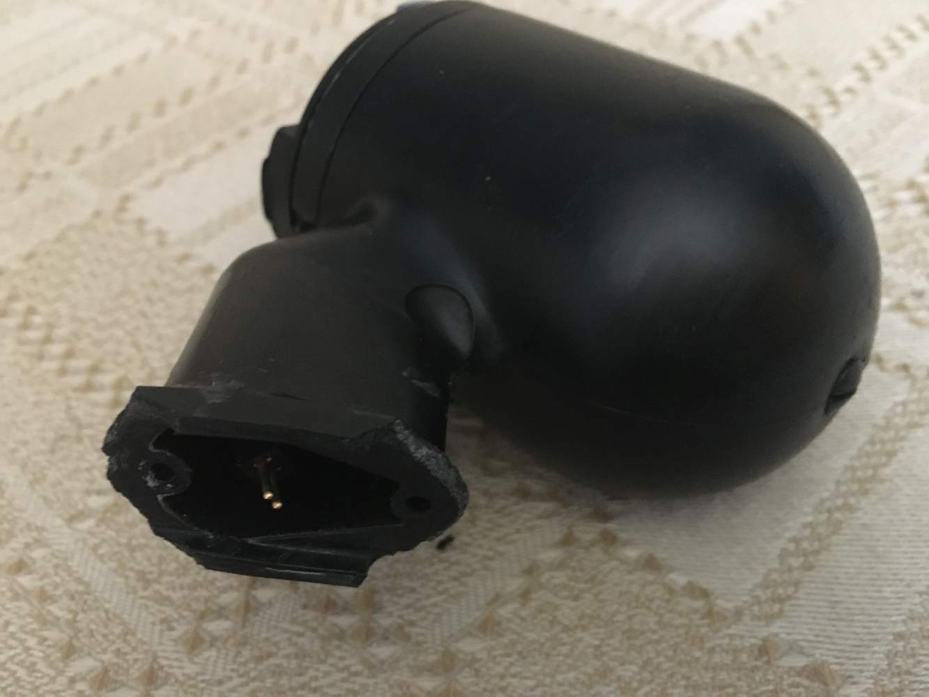
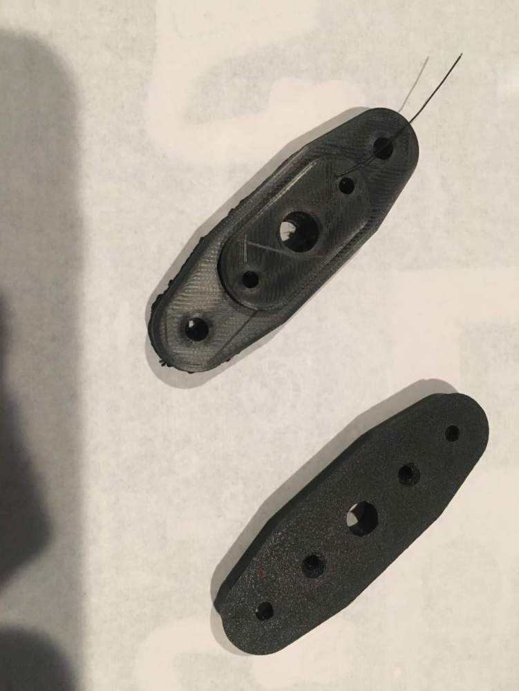
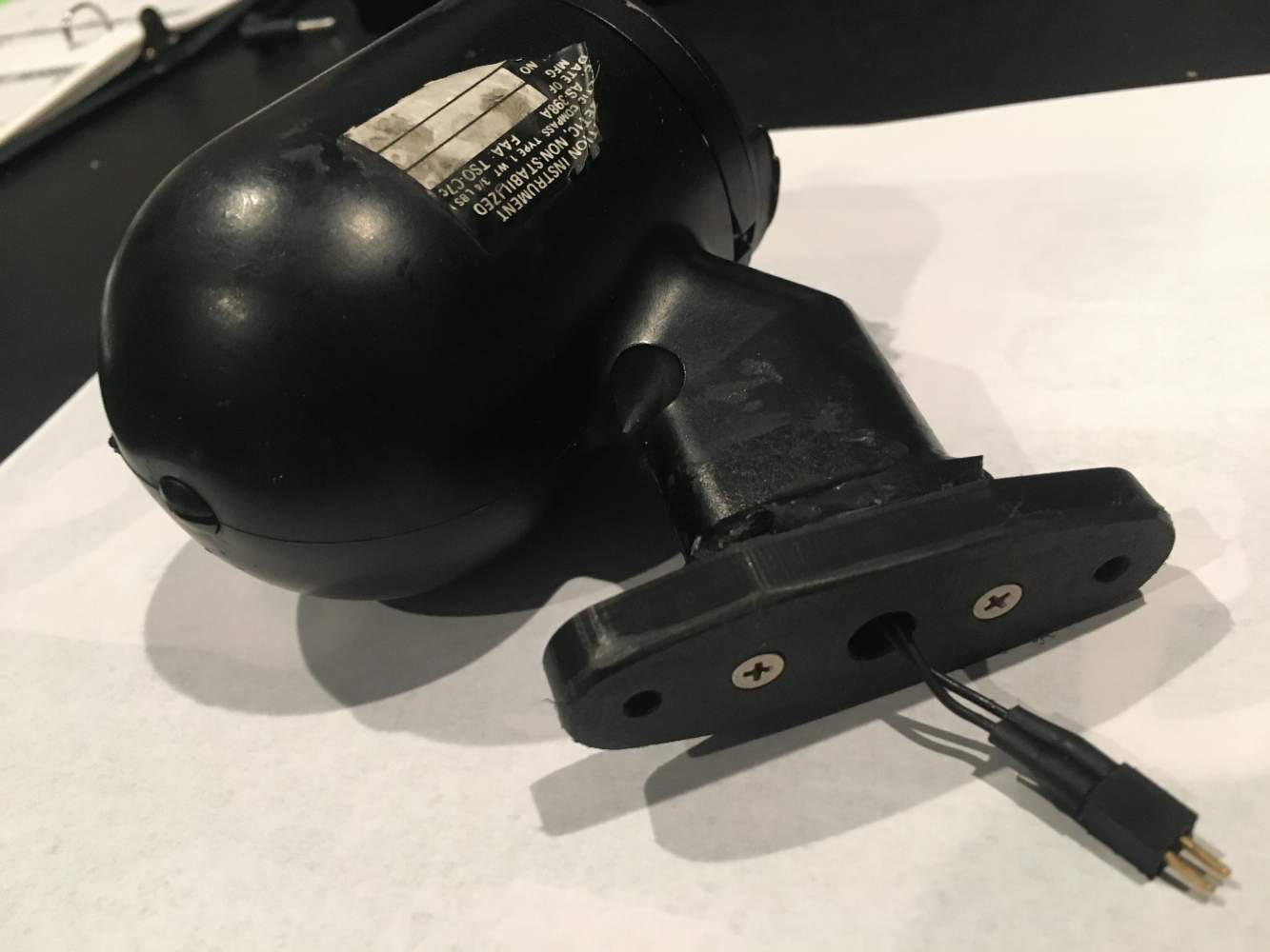
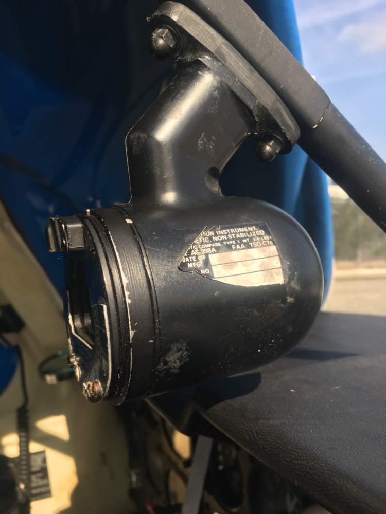
Folks: I don't know if anyone else has had this problem, but the mounting ears broke off of the compass housing. I believe it is made of Bakelite, and the material seems a bit crumbly after 40+ years. I have a good solution which involves a 3D printed adapter which I made. tapping a couple of pre-existing holes in the housing, screwing it on, and re-mounting the compass with original hardware. Here are a couple of photos: 1) the compass with broken ears. 2) top and bottom views of the adapter. 3) the adapter attached, and 4) the adapted compass re-installed. If there is anyone else in this situation, please advise and I will post the .stl file of the adapter and write detailed instructions to guide someone through the whole process. I am also just willing to send an adapter to anyone who needs it. Jer
-
I have a 2003 parts catalog as well. The gauge is listed in the wings section, page 57-30-01 (photo attached) as 880011-505 with no effectivity notes but with the notation see 28-10-00, which was posted by user "1980Mooney". That page shows the part number of 880024-5 with effectivity note /2. I was not able to see what the /2 referred to. Does anyone know the difference between the two part numbers? The question is fairly moot, since I have not been able to find either.

-
Don: I hate to be a pest, but his seems too good to be true. Just to confirm, you are saying the oval plate does not need to be removed? The entire thing can be accomplished from the top of the wing? The six screws around the perimeter of the gauge attach only the lower assembly and not the dial itself? Jer
-
Folks: I am sort of directing this to Don Muncy, who seems quite knowledgeable on this subject, but I would be happy to hear from anyone on the subject. Is the face replaceable by itself, or is it integral with the gauge, which would indicate the entire gauge to be replaced? What is involved as far as labor for the replacement? If that little oval panel it is mounted to needs to be removed, and since this is a wet wing, does the tank need to be drained and then re-sealed? Jer
-
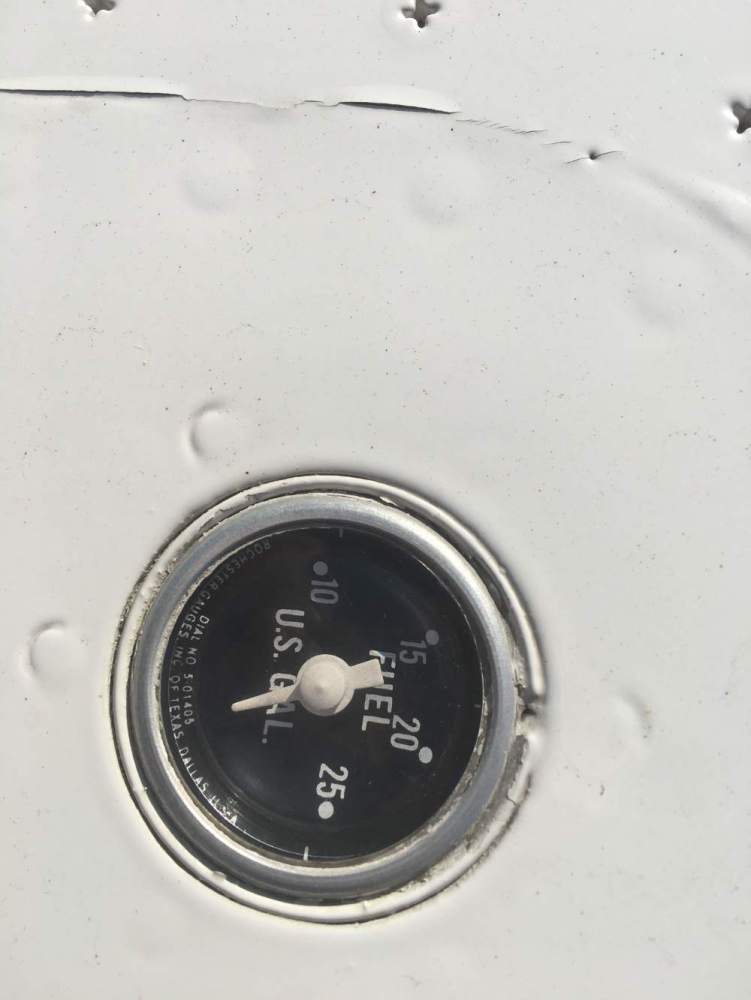
Folks: My "89 M20J, which I bought about 5 or 6 years ago, has a fuel gauge on top of each wing. When I bought the plane, they were both clear and easy to read. Since that time, one of the faces has become quite obscured. I made the probably incorrect assumption that my tie-down position subjected one more than the other to harsh sun. I assumed the face was cloudy as some automotive headlights get, and so I bought some plastic polishing compound and tried to buff it out. In doing this , it became apparent that it was not merely a surface condition, but rather the face was discolored through and through. The material now seems to be somewhat soft. I am suspicious that the material is being degraded from the inside by contact with fuel. Has anyone had any similar experience? Any suggestions for a path forward would be welcome. Jerry

-

Help me understand the use of the APU input on my 1989 M20J.
Jer replied to Jer's topic in General Mooney Talk
To answer a few folks: Mr Greg Ellis, thank you for the suggestion for training tools aside from the actual unit. When I said "antique", i meant it. It is a Garmin GPS155XL. It has a very different OS than one I am a bit more familiar with, a 530W. I had been recently flying a Bonanza with a 530W, and am now back to flying my Mooney, and I need to twist my mind back into the 155XL mindset. The Bonanza is the machine from which I removed the working 24V wet cell. I just didn't like the slimy condition inside the battery box. To answer member, 1980Mooney, I do not have a hangar. I am tied down outside, far from power. While operating the Bonanza, I had the need to start it once using an APU. The Bonanza POH specifically states to leave the "battery" switch off when starting using the APU. Note this is not noted as a "master" switch. I only did it once, and my recollection may not be correct, but I believe power was supplied to those normal things as turn coordinator, boost pump, etc. as well as the starter motor. After start, APU was removed, then battery switch turned on. This is where I got the idea that power might be available with the APU attached and the master off. I can only conclude that the Bonanza and the Mooney are wired differently and the "Master" switch is named differently than the "Battery" switch for a reason. Jerry -
Help me understand the use of the APU input on my 1989 M20J.
Jer replied to Jer's topic in General Mooney Talk
Eric: Thank you for your thoughtful and knowledgeable reply. I guess my suppositions were correct. The extra battery will help, but not eliminate the problem of battery drain during GPS exploration. Jer -
Folks: I recently removed a good wet 24V battery from another aircraft (replacing it with a gel) and decided to use it as an APU to allow for powering the avionics without engine start to let me gain proficiency on my antique Garmin GPS unit at leisure. My POH seems to be silent on the use of the external power plug, I have a set of jumper cables with clamps on one end and the big connector plug on the other. I plugged it in and expected to be able to leave the master off (thus not connecting the on-board battery) while being able to turn the avionics on through the radio master. This was not the case. The avionics did not power up. I assume I have to plug in to the APU and turn on the Master then the radio master. I did not do this as I thought it would be prudent to understand the situation prior to doing so. I am guessing that doing it as such, the two batteries would be essentially connected in parallel, and then turning on the master and radio master would still drain the on-board battery (although likely at a slower rate than unsupported by the APU battery). This is just my supposition, but I would like to hear from someone with knowledge of the situation. Thank you all for the help. Jerry
-
Thank you all for sharing your thoughts. Ibra commented that it was strange I ask about "half" flaps when the application of the flaps is continuous. I was really referring to "takeoff" flaps as indicated on the indicator, and as per other comments, yes I was contemplating throwing these in along with the gear when decelerating through Vlo in an effort to slow the plane. Per the numerous comments stating that the Mooney flaps don't offer much drag, I really don't see the point in pressing the issue. I must confess that recently I neglected retracting the flaps from the takeoff setting and got into cruise which exceeded Vfe significantly. The poor performance finally tipped me off and I retracted the flaps. I looked for damage and noted none, but I don't intend to do that again. Jer


