BrianW
-
Posts
78 -
Joined
-
Last visited
BrianW's Achievements
")


-

Overhaul outfit for Edo Aire DG w/ AP - 52D254 ?
BrianW replied to Flyler's topic in Avionics/Panel Discussion
I'd also let Mike (the guy that I communicated with at Rudy Aircraft) know that you are having issues with your contact pins. I would think they could easily replace any loose or worn pins. Perhaps have them inspect both the AI and your DG connectors. He seemed very fair, straightforward, and helpful. -
Overhaul outfit for Edo Aire DG w/ AP - 52D254 ?
BrianW replied to Flyler's topic in Avionics/Panel Discussion
Hi, I had my autopilot EDO-AIRE sent out to Rudy Aircraft Instruments for overhaul in 2025. Their price to overhaul was reasonable and they had a fairly quick turnaround (if I recall, it was like 3-day turn-around). I was happy with their work. Their website is very old-school and plain. The overhaul prices they post are for plain instruments not our EDO-AIRE with outputs to the autopilot. My autopilot enabled EDO-AIRE attitude indicator was more expensive, but less than $1000 for the overhaul. I'm not sure if I can post their website address, but they come up when you do a Google search for "Rudy Aircraft Instruments". They are in Arkansas. Call or email them for a quote for your exact model number of AI. It was a lot cheaper and faster than me thinking about a costly digital instrument upgrade. Maybe later I'll get that expensive Aspen Avionics, but not right now! :-) -
Hi, I have a 1979 M20J and over time I have gathered a number of documents that are rare and increasingly difficult to find. And with Mooney Corp not operating like they used to, and with old companies going out of business, it will become hard to maintain our aircraft without documentation. I have documents, manuals, and references that could be shared. Since most of these documents were already made available publicly online, or these companies ceased operations, and since this library would be for educational purposes only and not for commercial purposes, we wouldn't be in conflict with any copyright laws. For this to work, it would need to be moderated to be a searchable resource for Mooney owners and not to get filled with unwanted posts and messages - just owners manuals, service manuals, installation manuals, etc., for our aircraft and other aircraft stuff inside our Mooneys like avionics and autopilots. The library should have subcategory groups. Documents should be uploaded to a "review area" where a Mooneyspace moderator/librarian would then approve and post the file into the library. We are losing documents and knowledge, and we should make an effort to conserve the old information before it is lost. What say you? Would you share and upload docs for others? Would you appreciate a library to find for hard to find docs?
-
Easy mod to make glareshield access easy.
BrianW replied to BrianW's topic in Avionics/Panel Discussion
You can barely see them while sitting normally. I think they look like an OEM thing.
-
Hi, I wanted to share a super easy way to secure and remove your glareshield. The glareshield fastening screws from the top were a pain, and I didnt like a screwdriver touching the windshield. My solution was to mount a small "threaded rod" to each side of the panel at the original fastener locations. The threaded rods now help locate the glare shield from moving, and I can put standard thumb nuts on top to secure the glare shield down. Sorry I don't remember the exact thread sizes and names but you can look at the photos for the idea. You'll need: 2 long screws 2 screw clips 2 nylock nuts 2 black thumb nuts When installing the screws through the aluminum of the panel, you may need to bend the threaded rod/panel metal a bit to be have the threaded od more straight up and down. For me, I used a dremel to cut the head of the screw off, leaving the "threaded rod" - but you can still install this without cutting the screw head off. I hope that helps others here. :-)


-
Today I got back to the hangar. I removed to glareshield and started looking for the pair of transistors. I was searching with a flashlight and inspection mirror. They weren't behind the circuit breaker panel, not around the dimmer pots, couldn't see it within the console radio stack area, and not behind the pilot's panel. I inspected around the teeny tiny copilot fuses (see photo) but I couldn't see transistors on the other side of those tiny fuses. I suspect the transistors mat be the cause of dimming issues given my plane is almost 47 years old and we'll past the anticipated service life for the 2N2016, which is 10 to 30 years depending of service conditions. I would've liked to know/verify if my plane had the 2N3079, as stated on the drawing for my serial number, or if it was the older RCA 2N2016 which pairs with the 200 ohm resistor on my actual dimmer switch. I wish I KNEW where the pair of transistors were located to verify their part numbers. I don't want to turn this into a bigger job by cutting Zip ties to physically follow the wires from my dimmer switch to the transistors.

-
I have a 337 for my glareshield with LED light strip controlled by a PWM dimmer. But my incandescent lights still use the original rheostat-resistor-transistor for dimming control. I'd be happy if the original dimmer worked as it did when new, but it's 47 years old and I'm sure they are almost worn out. My M20J seems to be in a grey area. My dimmer uses the 200-ohm resistor although the drawing indicates it should be the later 50-ohm design. That's why I want to confirm that my installed rheo-resistor is paired with the proper transistor, but it wouldn't surprise me if they mismatched the components. I will look under the glareshield the next time I get to the hanger to search and confirm the transistor and its location. I never heard about PWM dimmers creating radio noise, but my King radios seem noisy, and maybe the PWM is contributing to the noise. I will keep that in mind the next time I fly. But less radio noise would also be a good reason to maintain the original dimmer setup. I found out that Mooney produced a Mooney Transistor Mod Kit 919003-907 to change the transistor from the RCA 2N2016 to the Delco 2N3079 involving rewiring the rheostat and changing the resistor and replacing the RCA with the Delco transistor. The best that my research could find is this partially obscured instruction sheet and a picture of the parts included in the kit (see attached). Unfortunately, I can see it is a 3-page instruction, but I only have this image of page 1. Is there a resource where we could find the complete 3-page instruction sheets for the Mod Kit 919003-907? I am hoping that if I have the RCA 2N2016 transistors that I can test them to ensure they are still working as intended. Otherwise, I may need to source new-old-stock for the 2N2016. And if the 2N2016 is out then I'd have to look at upgrading. Did Mooney ever specify a silicone-based replacement transistor?


-
I looked under the copilot panel at the dimmer switches and did not see the transistors there. I only saw the wires from the dimmer potentiometers going to the black wire harness connector. On the other side of the copilot panel, below the circuit breaker panel, I saw the 4 mini fuses but did not see any transistors around them. Where are these transistors typically located? My plane is a 1979 M20J. I just want to confirm whether I have RCA or Delco transistors. Thanks.
-
Can you explain what you mean by "they are high side with npn"? The drawing showing the resistor 2N2016 looked like an error to me. It seemed emitter "E" and the collector "C" were reversed. I scrutinized the schematic drawing tracing the positive and negative leads. I also reviewed NPN and PNP transistors and the designed current flow directions for these transistors (and correct me if I'm wrong): In an NPN transistor, the current flows from the collector "C" to the emitter "E" when the voltage on the Base "B" goes from 0 to positive. In an PNP transistor, the current flows from the emitter "E" to the collector "C" when the voltage on the Base "B" goes from positive to 0. So, the current flow direction and the labelling of C and E of the RCA 2N2016 transistor appears correct. But the Delco 2N3079 transistor (for later model serial numbers, s/n 24-0927 and on) seemed wrong. The Delco 2N3079 is an NPN transistor as well, but it has the C and E terminals reversed in the Mooney schematic, as if it was a PNP transistor. But in that case the B terminal would need to go from positive voltage to 0V in order for the lights to come on which is opposite from the way the dimmer potentiometer is wired (the panels lights do not come on when the dimmer is switched off). So, the current flow direction and the labelling of C and E of the Delco 2N3079 transistor appears incorrect. I will check my M20J today to see if my original transistors are RCA or Delco. Hopefully they are the RCA's.
-
For the benefit of others, I've attached the original Mooney electrical schematics for the M20J (for my serial number range). I've marked up the drawing to trace out the panel light circuits and to identify what is being dimmed. One discovery that I made from the drawing is that the compass light is connected to the on-off switch portion of the dimmer. That means that when the dimmer clicks on, the compass light gets full 14v power but cannot be dimmed. The other goofy thing was the center console lamp. The console lamp is on the glareshield dimmer circuit. That's weird because unless you fly with the glareshield on, your center console lamp will be off. I need to verify if the console light is the light for the flaps indicator. It that the same for other M20J owners? I understand why the glareshield would be separately controlled from the rest of the panel lights (because I normally don't fly at night with the glareshield on). But I can't think of a reason why Mooney wanted the console light to be grouped with the glareshield and separate from the rest of the panel instrument lights. I would think it makes more sense for the center console light be grouped with the rest of the panel lights and then the glareshield would be on its own dimmer control circuit. Additionally, I would prefer that the power to the compass be dimmable, so that if you had a bright compass light, you could dim the brightness down to protect your night vision. M20J Schematics Dimmer Markup.pdf
-
Thanks Mike. That's more great information.
-
Thank you for the additional information. I read through the FAA interpretation letter and on the surface, it states that in 14 C.F.R. part 43, appendix A, paragraph ( c ). the 32 subparagraphs that define the preventive maintenance tasks are not considered "controlling" or limiting of all the potential preventive maintenance tasks, the 32 subparagraphs are considered as examples of preventive maintenance tasks. The FAA letter further states, "Advisory Circular 43-l2A, Preventive Maintenance (which was referenced in Mr. Hernandez's letter), is overly restrictive. That sentence, found in Paragraph 3(b)(l), states: "If a task or maintenance function does not appear in the list, it is not preventive maintenance." As with the other paragraphs of Appendix A (i.e., on major repairs and major alterations), the lists are better viewed as examples of the tasks in each category-they cannot be considered all inclusive. There are, no doubt, many "simple or minor preservation operations [tasks]" and many "replacement[ s] of small standard parts not involving complex assembly operations" performed daily, especially on small general aviation aircraft, that the agency would consider to be preventive maintenance, though they are not included in the 32 listed items". That is an excellent section of the letter. I am now looking at an intriguing "rabbit hole" and deciding whether to jump down the rabbit hole. The letter states, "It is our understanding that Flight Standards' Aircraft Maintenance Division is planning to clarify this issue in a future revision to the AC". Was there a clarifying AC that was subsequently released?
-
Hi, I'd like to share my journey... I have a 1979 M20J. I am an owner pilot and engineer. I want to keep my M20J as original as possible. So, here's my next "squeaky wheel" in my plane - the worn-out dimmer switches. My dimmers are now around 47 years old. That's a great service-life for a moving component! But alas, the old dimmers are no longer smoothly dimming. The dimmer adjustment has "dead spots" and need "finessing" to operate. I know there are some here that love paying lots of money for "its aviation, you need to add one or two zeros to the price". But I'd rather find the exact replacement part for $9 if they are available. And that brings me to my project... Looking at the Mooney Service Manual and wiring diagrams for my serial number, the dimmers are standard common parts. Or least they were back in 1979! The dimmer consists of a rheostat (potentiometer) and resistor. The rheostat was produced by Allen Bradley which stopped production over 20 years ago. The rheostat (potentiometer) cannot even be located in used parts or secondary resellers (i.e. eBay, etc.). The resistor is likewise unavailable anywhere. At least the company producing the resistor is still in business - Ohmite Manufacturing. I was able to find Ohmite's cross reference from legacy part numbers to their new part numbers. Using engineering data for the original resistor and potentiometer, I was able to confirm the new resistor part number is the identical component. The specifications for the potentiometer made it challenging to locate an identical commercially available replacement part. With lots of searching I was able to eventually locate a manufacturer in the US that produces aerospace parts and has a commercially available equivalent potentiometer. It is operationally identical; the only real difference is the control shaft is a 1/8 of an inch longer than the original Allen Bradley potentiometer switch (meaning the dimmer control knob would just stick out 1/8" further from the panel). I put a call into the local FSDO to get their feedback. I spoke with their inspector and was told several methods to make sure that the replacement is compliant. I asked, as the owner and pilot if I could replace the dimmer as "Preventive Maintenance" since these are common parts and do not involve complex assembly. I felt that if the PMA dimmer switches at Aircraft Spruce state that the Owner/Pilot can install their PMA dimmer switch with only a logbook entry, then replacement of dimmers are not considered complex and do not require FAA certified installers or special inspections. The FSDO inspector felt the question of "owner/pilot replacement as preventive maintenance" was a good question. He didn't know the answer to that off the top of his head. We discussed possible compliant routes to getting the dimmer replaced. He mentioned that if it was installed by an A&P with a 337 then it would be compliant. I definitely agreed that the 337 route is a solution that I'm considering. Another solution that I considered was getting it PMA approved. That's a lot more work but I was thinking of potentially doing this as a small business, assuming that other Mooney owners have worn out dimmers with no other option other than expensive PMA solid state dimmers. The inspector also said that if the manufacturer allowed these as substitute part numbers, then it would be considered part of the type certificate and be considered approved replacement parts. With Mooney struggling to remain open and with so many Mooney Corporate changes, I don't know if Mooney is actively operating at this point in time. However, I put a call into Mooney technical support and left a message for a call back. I don't know if that will yield any results. I'm sure that I can get this done in accordance with regs. I am just looking for the least cost (and fun) solution. I'll post an update if I move ahead with this.
-
I love the Pre-Madonna! That's before her first album! :-) I think the expression is "Prima Donna" meaning "First Lady" or the leading lady opera singer - now meaning a temperamental, egotistical, and demanding person who expects special treatment and attention.
-
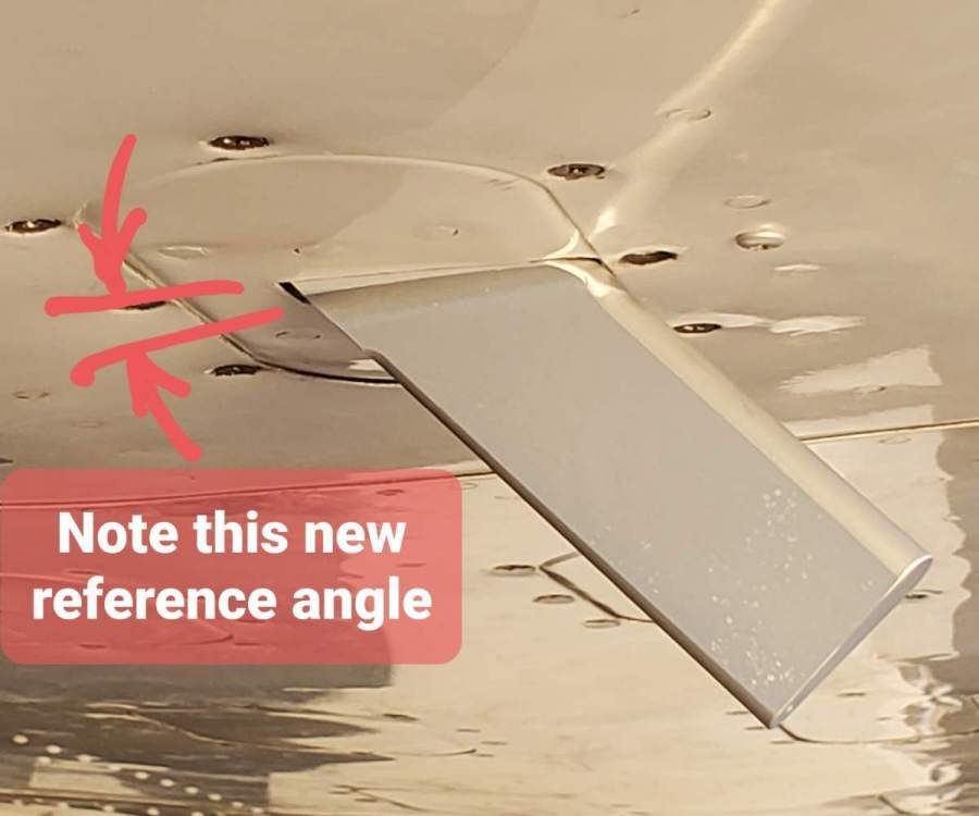
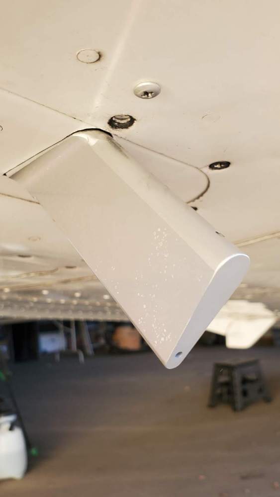
After talking with Bendix Technical support, I was told Bendix stopped selling the KLR10 in 2013/2014. Bendix had limited technical information but said the KLR10 was actually produced by Alpha Systems for Bendix. They gave me Alpha System's phone number. I went over to Alpha System's website. Our KLR10 is equivalent to their "Eagle" kit. They had much better documentation for installation and calibration. I spoke with (I think it was Mark) at Alpha Systems. He explained the operation and calibration procedure. He said the probe angle moves at 5 degree increments. He called this the "coarse adjustment". The calibration button sets the "fine adjustment". He said that based on the OAA showing the blue circle and yellow bar below (when it said "invalid set point") meant the probe was angled down too much, and that the probe tip needed to be rotated up 5 degrees to the next locking point, and reattempt the calibration again. I'm glad I spoke to Alpha Systems for clarification. In order to rotate the probe tip up, I had to increase the hole size that the probe goes through on my wing inspection panel at the front. I had to Dremel out about 1/8" material from the access cover at the front of the probe and rotate the probe up. (see photos). I flew the plane and it calibrated easily at the 1.3 Vs for OAA calibration. By the way, the choice for the probe location was in the right wing access panel. There was nothing behind this access cover that requires the removal of this access cover for the regular annual inspection. The only thing I would have changed would be to cut the probe hole NOT in the center of the cover plate. I would move the probe 1" left or right of center. At center, the front center screw gets blocked by the probe (see my photo) and will not allow the use of the center screw. Also, I'd shift the inside probe mounting flange as rearward as possible so when you remove that little bit of material in front of the probe (to allow the probe to be rotate up a bit more) the probe hole would not be so close to the front of the access cover hole (you can see its close in the photo). I'd prefer the front/back placement of the probe hole to look more centered in the cover plate. This AoA works great now. I'm happy with my AoA now. But Bendix no longer sells and supports the KLR10. Alpha Systems have continued to get better and have great upgrades, accessories, and support. If you want an AoA, I'd definitely choose an Alpha Systems unit.