Search the Community
Showing results for tags 'm20f electrical amp connector'.
Found 1 result
-
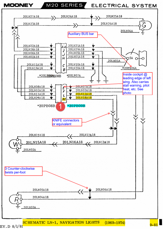
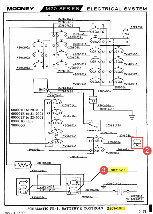
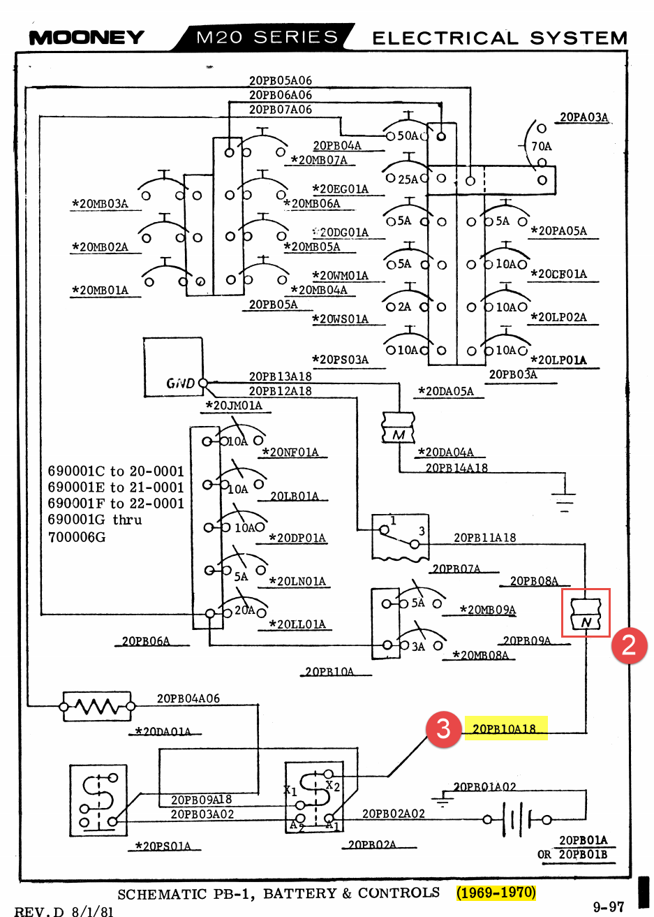
 Hi all, Note/Edit: After seeing @carusoam's post below, I just wanted to clarify that we are working with an A&P on this project and so we need everything done up to a quality that he will sign off on... We are the (two) new owners of a 1969 M20F (N9150V) which we bought in December from @Stephen after we found his posting here on Mooney Space and after @Culver LFA ferried it from MO to Oakland, CA. Its a nice flying machine, but like anything that age it has a few things we need to deal with. Right now we are working on a tail nav/strobe replacement and could use a little advice both on resolving the initial problem and then the problem we created when started "fixing" things. Issue 1: Tail NAV light is out, plastic is damaged. Initial diagnosis: Light assembly is old, maybe has water damage and has failed. Solution: Replace it with a Whelen Orion 500v. Result: Strobe works, NAV light still not working. Debugging1: The voltage on the strobe is ~12v and the NAV light works on this as expected. The voltage on the NAV circuit is sometimes 9.5 or maybe 11.5 or maybe 8, but always varying moment to moment. When connecting the NAV light to the NAV circuit the votage drops from whatever voltage it was showing down to 1 or 1.5v. Analysis: OK so we should have done this test before buying a replacement light(!). I looked at the filament in the incandescent bulb and verified it was not broken and so I *assumed* that the internal electronics had failed and did not consider or fully test the circuit itself. Debugging2: So initial troubleshooting shortcomings aside, we were able to determine that something was going on on the positive side of the circuit and and started to dig into the NAV light schematics in the maintenance manual (page 9-81 image below) to start breaking it down into bite size chunks. We already had verified that there was no continuity and extremely high resistance from the NAV light switch to the tail. So the first chunk was to test from the tail to the first connection (#1 in "Schematic LN-1" screenshot below) where we verified continuity and measured very low resistance. We noted a little bit of corrosion in the pins (#5 in photo below) and sprayed it with electrical connector cleaner and wiped the mail connectors as best we could. So first section was tested good, from the plug (male) connectors to the tail cone... Then umm... wait a minute, why is that dangling wire there? Wait, why is the master switch no longer turning the power on? OK, we can no longer work on issue #1 because we need to address the problem we just created which is... Issue2: Total electrical power loss/master switch no longer turns on power. Analysis: Dangling wire labeled "20PB10A18" (#3 in schematic below, #6 in photo below)) was connected to "N" hole in receptacle (#2 in schematic PB-1 below) became brittle and broke off when we disconnected (and wiggled and moved around) plug 20-PB09B (#5 in first photo below) from receptacle 20-PB08B (#4 in 1st photo below). (Would be) Resolution: Remove pin with jury rigged extractor and replace it with um, a thing um size um... and this is where we get stuck... Questions related to issue #2: What size pin is this and where does one go to find a replacement? I am sure if I had the size I could find it, but a supplier name could be helpful. Also, these were crimped rather than soldered which surprised me- thoughts on the replacement? If the wire seems to be too brittle over more than just the last quarter inch when we strip it back, should we consider replacing the length? If so what is appropriate wire/part number for that? How do we go about labeling it for posterity? Now that that is settled and power will soon be restored we can get back to the original issue... Meandering Thoughts and Questions related to issue #1: Having isolated and confirmed continuity downstream of the plug, the problem is either the contacts within the plug/receptacle assembly of upstream to the switch. Left and right NAV/strobes are fine and both go through that connection. Access to the second "flight panel" plug/receptacle (Schematic 1- 20LP06A/20LP07A respectively) is pretty onerous. In fact, while I can see up into the rats nest of wires behind the panel that there are a couple of candidate connectors, it is unclear which is which and how one would go about disconnecting them- there just is not any real access or good visibility. Maybe I am looking in the wrong place. To bypass access issues and having to dig the hole we are in even deeper, would it be a legal approach to go straight from the NAV switch, which is accessible, and put in a new wire that goes directly from there to the receptacle side of #1 in the upper schematic- in other words when re-wiring something does it need to be replace a like with a like? And regardless of legality, would it be unwise to that? I can't see anything about that that would be unsafe and that would make it a much more painless speedy fix. And are there better (AMP?) connectors that the black plastic ones- should we consider replacing the assembly now that we have it out- that seems like if might be more trouble than its worth, but would not want to waste the opportunity if it should be done... One step forward, two steps back... Any advice on how to proceed? Johnny