MV Aviation
-
Posts
74 -
Joined
-
Last visited
Recent Profile Visitors
4,572 profile views
.thumb.jpg.c1755c6f2a5ddfc3ae808a298bc39505.jpg)


MV Aviation's Achievements
")


-
Hi everyone, I'm posting this here, since it makes most sense in the Europe section... I used to be a proud M20E owner until my plane had an accident last year (no I injuries!) and is beyond repair. I’m therefore selling the 64gal Griggs bladder kit, which was installed in late 2019. So it’s pretty much like new. There is no damage due to the accident. All hardware is complete (although not everything is shown in the picture). You only need a few rivets and gaskets. The original 8130-3 and installation instructions can be provided. I’ll consider any reasonable offer please PM me, if interested. Based in southern Germany. Marco

-
I’ve done my mains according to the way suggested here. It worked pretty well despite the fact that the collar bolts were put in the wrong way last time, which made it impossible to remove them without disassembling the gear doors. I recorded a little time laps… IMG_0867.MOV
-
Thanks for your feedback. Regarding the increased HP: the engine will not produce more HP than it is rated for. The more dp the filter "produces", the less the engine will be able to freely breath and the less HP the engine will produce in a given environment. Since the filter can be bypassed altogether in my Mooney, there's no need for flight tests. A little "better" filter would lie somewhere between the "worse" filter and "no" filter in terms of pressure loss and engine performance. The Brackett filter is messy. The sticky stuff runs out during flight and messes up the lower cowling and gear (especially when flying in rain). Also (in Europe at least) it's relatively expensive. As long as the Challenger filter survives its 2000h, it will be cheaper in the long run. Okey, there is some added labor for cleaning and re-oiling, but cleaning the mess of the Brackett filter is equally annoying.
-
Hi! I've just upgraded my M20E from the filthy sponge-type air filter to a challenger (STC) one. They do advertise an increase in HP on their website. This is accomplished by a smaller pressure drop across the filter. Since my E has the power boost feature, which bypasses the air filter, I was able to precisely measure the pressure drop of the old filter by opening and closing the power boost and observing the MP. I've measured it a couple of times at different altitudes an always landed around dp=1" MP. With the challenger filter installed, I repeated the test and got roughly the same dp, hence, not performance increase with the new filter. I think I remember (not sure where I read it) that the pressure drop of the challenger should only be in the area of 0.3”. Has anyone of you done the same conversion and measurement and can confirm or refute my values? Best regards, Marco
-
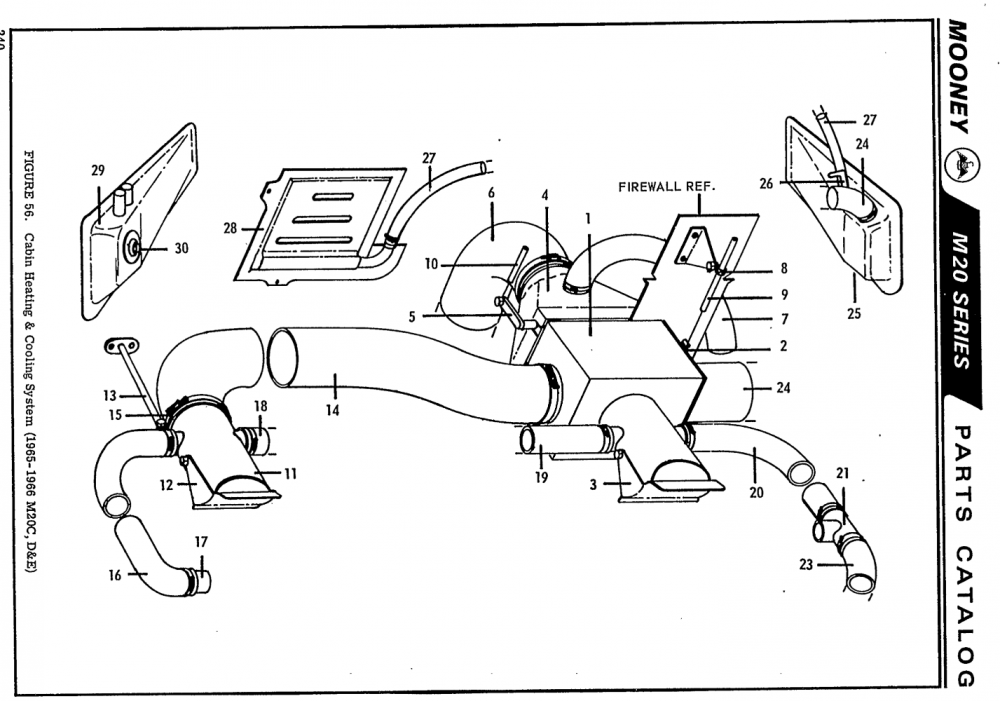
Hi, does anybody have the different diameters of ducting in a mid'60s E model on hand? The IPC is not very helpful in this matter. Thanks! Marco
-
Where do Eurpoeans take their Mooneys for maintenance?
MV Aviation replied to Awqward's topic in European Mooney Pilots
I bought my Mooney through Troyes. They did the pre-buy and got it back to airworthiness after it was stored for a year. They were not cheap, but they did a good job. Have only used them that one time. -
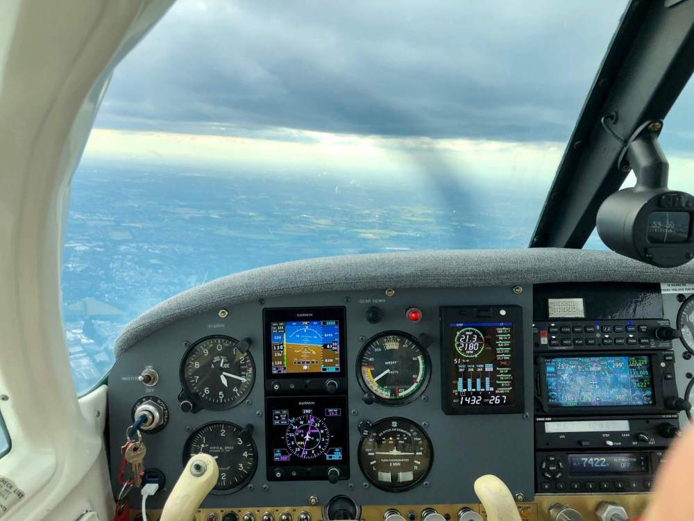
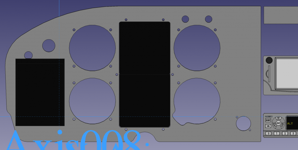
The S-TEC TC is too long to fit in the lower left position due to a tube running across behind the panel. Therefore I mirrored the entire layout left to right. I really don't care, as I now only look at the G5s inflight. No need to make any of the classical scan patterns.
-
I've completed the install in May. The grand total for all hardware was about 6.5k€ including the new panel. Labor was provided all by myself (including CAD of the panel etc). With everything prepared in advance (like harness, panel cut, ...) it took me 7 days with 12h of average work per day to do it including all necessary calibration and testing. Riveting a bracket for the magnetometer into the wing was a bit of a pain. Everything else was ok. The aircraft lost about 5kg net in vacuum system stuff, old instruments and the vacuum retractable step. I'm totally satisfied with the result.
-
A 4 cyl engine will definitely not run smoothly on three cylinders, not even on 3.5 cylinders. On the last flight with a partially clogged injector, I managed to go approx. 50°F LOP on the faulty cylinder and about 100°F ROP on all other cylinders. That was sustainable in cruise, otherwise I would have aborted the flight. Going any leaner introduced vibrations on the clogged cylinder and "shutting it off" by going even leaner, would not have been pleasant at all. On a 6 cyl engine on the other hand, I can imagine running wit only 5 is ok.
-
Thanks for all your reports. I will have a look at the screen next. I haven't had any problems like that in the past 4.5 years I owned the Mooney. And, as said, the bladders were freshly installed 1.5 years ago, so sealant cannot be the source of the issue. This incident taught me that a digital engine monitor is worth a lot. Troubleshooting would not have been as straight forward as it was without it. Also, watch EGTs during run-up! Although temps are not close to peak at 1700rpm and full rich, some issues can be identified while still on the ground.
-
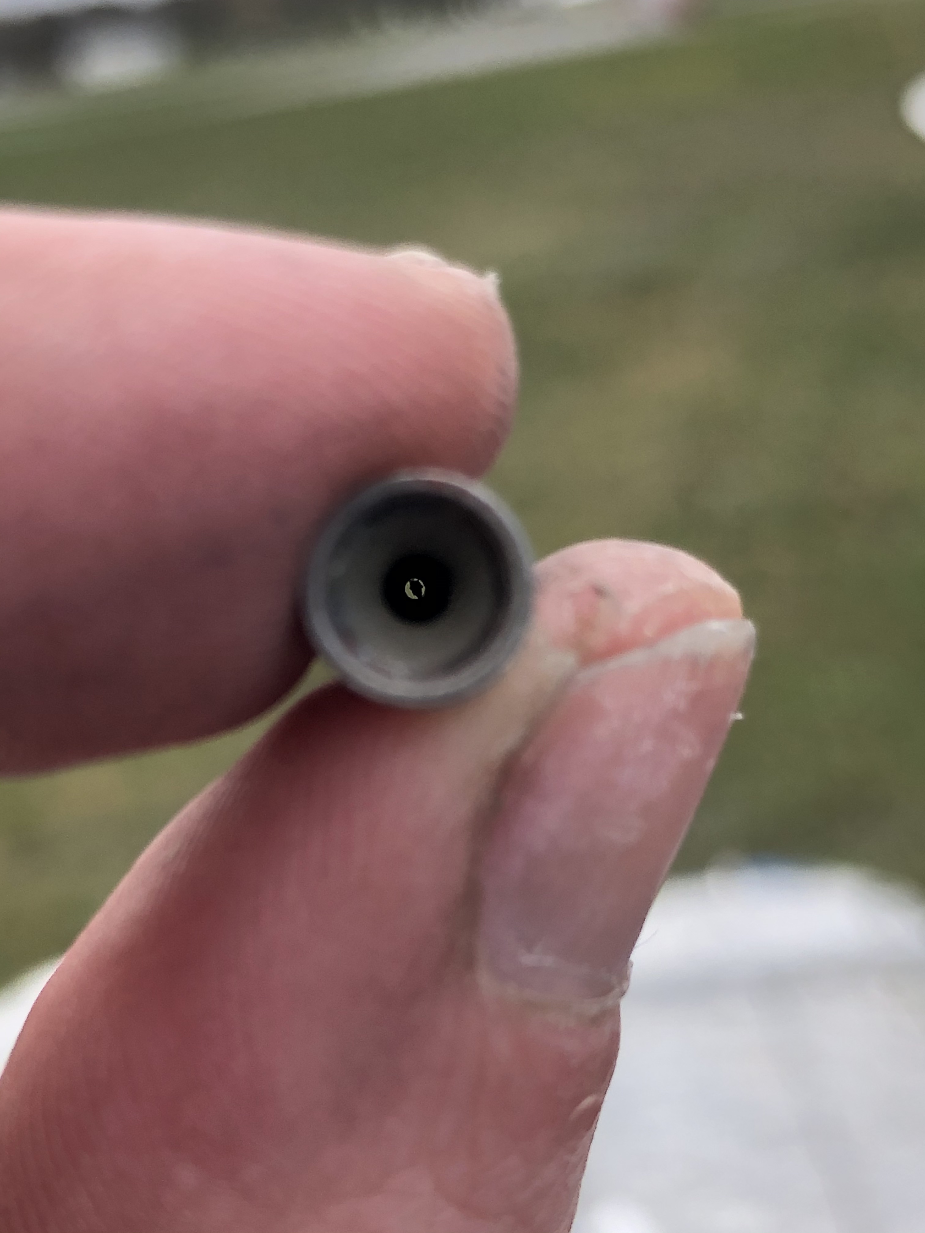
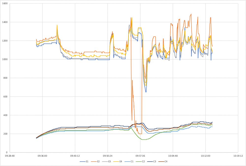
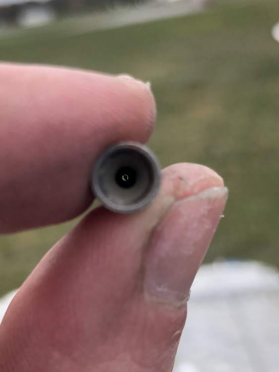
Hi everybody, I own a M20E, which has a fuel injected IO-360, with which I've recently experienced some recurring issues. It all started with an engine start on a relatively cold day (sub freezing). Not sure if that has something to do with the issue, but I mention it for completeness. Anyway, engine start and run-up went well. I took off and shortly after takeoff in about 300-400ft AGL experienced some extreme engine roughness. I immediately pitched down, pushed the mixture full forward, engaged the electrical fuel pump and after a few seconds with no changes in the symptoms, decided to return immediately. On my EDM830 engine monitor I noticed that cylinder no 2 wasn't making any power. You can see that on the graph below. The orange line is C2 EGT, while the green one shows C2 CHT. EGT drops almost instantly, CHT follows slowly due to the thermal mass of the cylinder itself. After landing I did a couple of checks (extended run-ups, played with the mixture, etc.) and still saw that C2 wasn't working correctly, although it came back and made some power. The higher ETG suggests that C2 was getting less fuel than the other cylinders, therefore, during hotter. My first guess was that some water may have frozen in the fuel line leading to C2, which is exposed to the cold environment on takeoff. However, since the problem continued on the ground, with a warmed up engine from the take off and no air speed, I dismissed that theory. Long story short, I eventually unscrewed the C2 fuel line from the injector and found it to be clogged with a particle similar to the photo below. I cleaned the nozzle in acetone, like a Lycoming SB recommends. After putting everything together, the engine worked normally again. Some uneventful flights later, I experienced a similar behavior (this time on a warmer day) but on cylinder number 4. The engine wasn't shaking violently, like the first time, but the issue was observable on the EDM. I normally fly LOP in cruise, but with C4 reaching peak about 200°F earlier than all other cylinders, LOP was no option. Flushing with the mixture didn't help. Again, I opened up the injector on C4 and found it to be partially clogged (attached picture). This time I kept the particle and checked whether it was magnetizable, which it was not. Hence, at least I know its not a variant of steel. Overall it seems like some component in the fuel system is, from time to time, loosing particles with a size that is able to clog the injectors. Does anyone have experience with anything like that? Could it be the inside of a fuel hose that is dissolving? Btw. draining the tanks never revealed any significant debris in the tanks and factory new bladders were installed only 1.5 years ago. Happy landings! Marco
-
M20E panel renovation & layout
MV Aviation replied to MV Aviation's topic in Avionics/Panel Discussion
This is, what I ended up doing ... EDM830 goes in the top right (I did not do the rectangular cutout for the 830, because I might exchange it for a 900 at some point) and the six pack layout is mirrored left to right so that my TC goes in the bottom right, airspeed above and alt + VS on the left. And the USB ports go in the bottom left, below ignition and master. Let’s hope it all fits. thanks for your advices!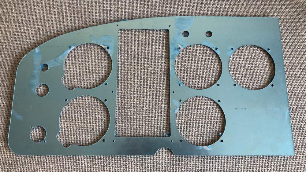
-
M20E panel renovation & layout
MV Aviation replied to MV Aviation's topic in Avionics/Panel Discussion
Thanks for your comments and suggestions. Why are some of you tending towards a standby AI? The whole purpose of the dual g5 is, to get rid of the vac system. With an electrical TC gyro that incorporates the autopilot, partial panel in an emergency should not be an issue. -
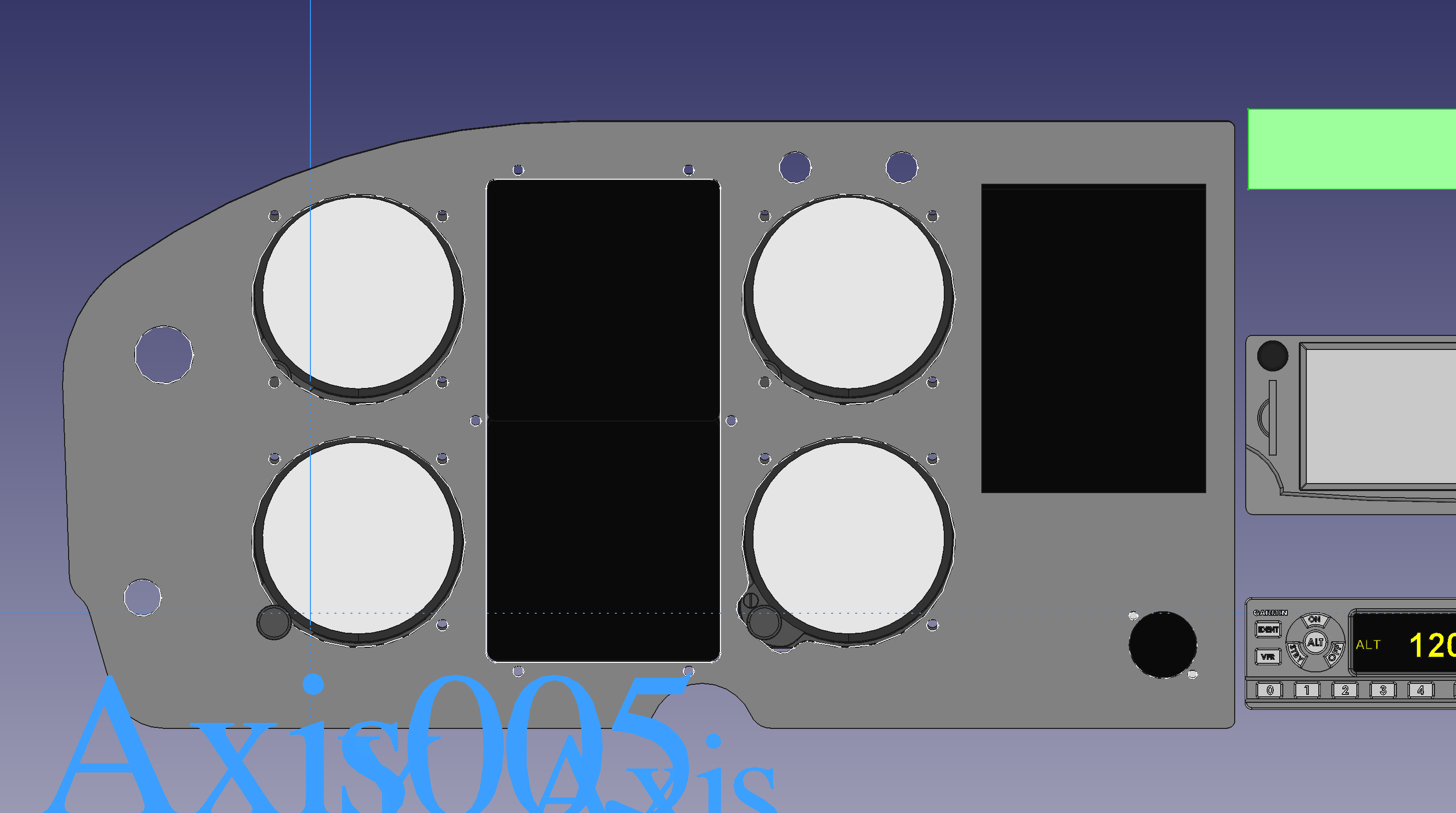
Hi Folks! I have a hard time deciding, which layout works best for me. Down below you'll find two CAD images with the pros and cons. Maybe you have some additional input for me to consider. From the arguments, you may notice that I favor version B, but it is a bit of a waste of space. Version A pros - makes the most out of the panel area and leaves some room for smaller add-ons in the future, although I don't know if I'll ever need that. - somewhat of a standard utilization of the panel with potentially eight instrument positions. cons - the G5s are not in the center of the panel, directly overhead the yoke (I dislike that). - the S-TEC30 TC, which for a standard layout would go in the lower left position, will not fit there due to its protrusion behind the panel and a collision with a tube of the steel cage crossing behind the panel. Hence, I'd have to swap two instruments, which is a deviation from the standard six pack. Version B pros - standard six pack layout will work with the TC in the lower left. - G5s symmetrically overhead the yoke (I like that) cons - waste of panel space on the right. - the engine monitor is somewhat cramp into the left corner and I'll have to first figure out whether that works at all. Otherwise it goes back to the right panel and leaves some unusable space behind. If the engine monitor did fit in that spot, the keys of the ignition would hang down on it (would be fixable by moving the ignition to the right panel edge, although, that's an unusual location).

-
Vintage Mooney PIC panel tilt
MV Aviation replied to MV Aviation's topic in Avionics/Panel Discussion
Negative. What I've measured no is this: PIC panel angel SIC panel angel On ground 3° forward 11° forward In flight 6-7° forward 14-15° forward So, neither panel has 0°, neiter in flight nor on the ground. The left panel might reach 0° (and even negative °), when I pull up the nose on takeoff or flair on landing. That it is only 3-4° nose down from ground to level flight, surprised me a little. I expected a bit more. According to its PN, the STEC TC requires a 0° installation. Guess what, that's how I measured it ;-)