47U
-
Posts
821 -
Joined
-
Last visited
-
Days Won
1
Content Type
Profiles
Forums
Blogs
Gallery
Downloads
Media Demo
Events
Status Updates posted by 47U
-
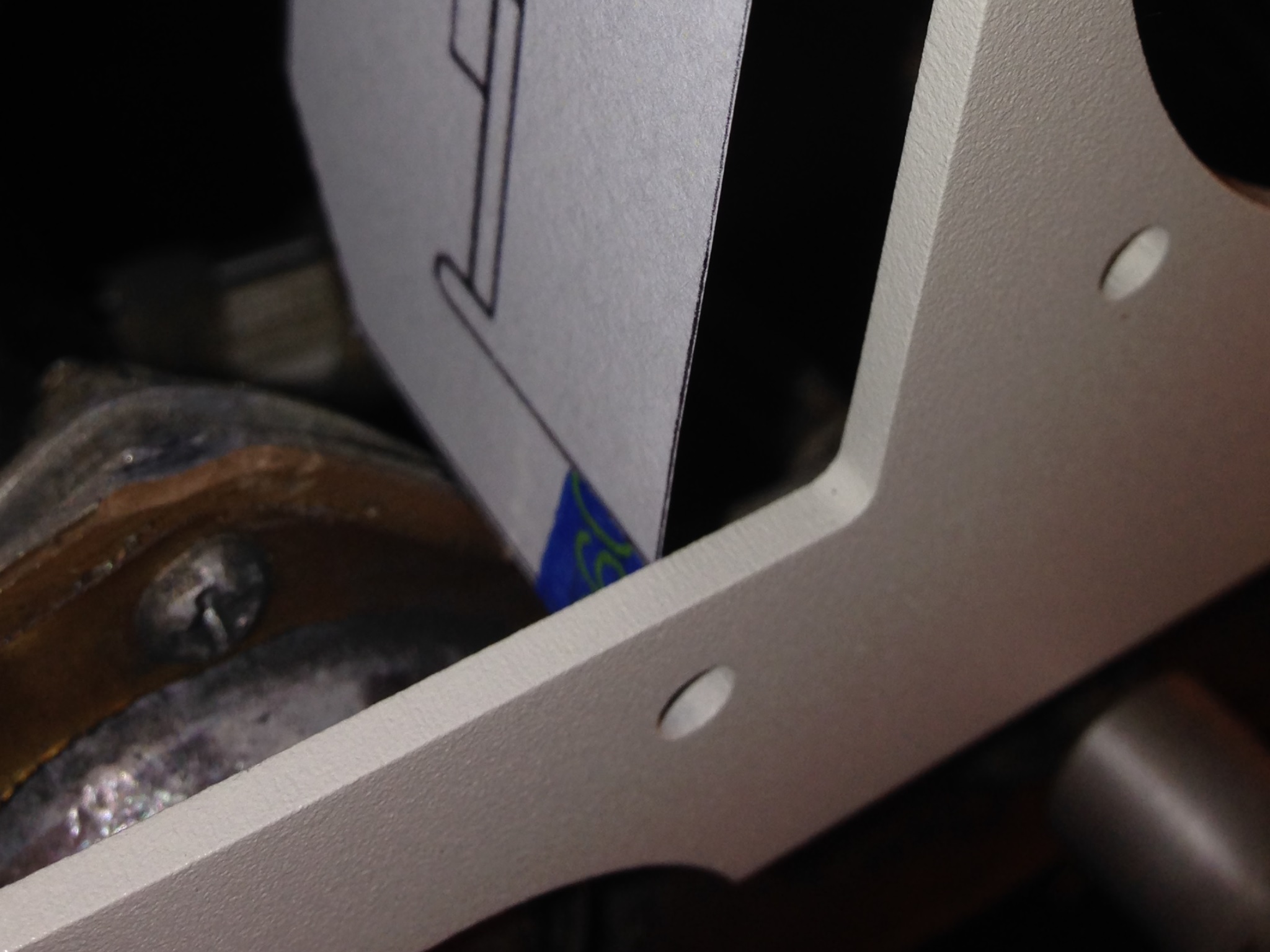
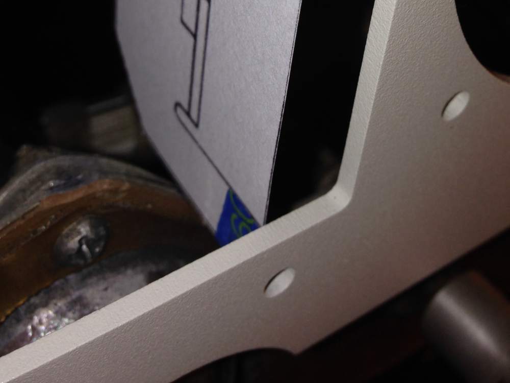
Igor_U, Yes, Aspen flush mount. The Aspen cutout dimensions are in their install manual, available online. I ended up recutting the panel shown in the thread picture. The Aspen component that would go in the bottom hole (of an Aspen upper/lower two-hole surface mount) is much smaller diameter than a standard 3 1/8" instrument so there's no yoke tube interference, but I found the Aspen flush mount bracket was too close to the yoke phenolic ball mount and I didn't like it. (I cut out a template from card stock.) It wasn't touching, but I couldn't pass a credit card between the Aspen mount rail and the ball assembly. So I moved the Aspen up in the panel about 1/4", recut the panel, and now it's fine. Beware that powder coating might decrease the cutout dimensions slightly and cause an interference fit. I had a buddy do the CAD changes and should have increased the dimensions a thousandth or two. Same for the round instruments... laser cutting is very precise. Everything fit pretty tight after powder coating whereas it was perfect before. I probably should have masked off the holes to keep them clean metal.
- Show previous comments 4 more
-

Thomas,
I really appreciate your help. I opened .dxf file at work using CATIA V5 and transfer it to .CATDrawing V5 native file. As you said, it is what the PDF was created from, just no dimensions.
I have a question, though. Was this design done in mm? I’ve opened it on my machine that is set to inches and dimensions are just over 440 for a 17.35” panel so it must be. Definitely it’s scaled 25.4X.
No mater, I’ll use your PDF file and dimensions of the upper contour.
I have already created a 3d model of my panel but I know I didn’t have the right contour so your PDF will help.
BTW, I work in as Design Engineer in Aerospace, currently contract for Gulfstream but was years in Seattle for Boeing and small design firm that subcontracted us to Boeing, Bombardier, Lockheed etc…
My plane is home at KPAE (where widebody Boeings are made) so really work will be done when I get a job back home and have more time for that.
My plan is to go with 8-hole but modified for 2 G5s. Those need 7.2” tall cutout so it’s somewhat more than Aspen but there should be enough room.
Instead of full size 9th hole, I’d like to have 2.25” hole for new clock; 8-day clock in yoke can be covered by iPad and such.
Originally, I wanted to buy panels from LASAR but now I think I might go custom and start with 8-hole as baseline. I might still go with LASAR, at the end.
My concern was excessive trimming of substructure as you described and read years ago from Johnathan Paul in his internet post.
Also, with 2 G5s I can get rid of the DG and ILS/VOR1 and I still keep the AI at top right location where ILS would be. Or move it to the right panel if I decide to move my Primary engine monitor closer, to pilot’s panel.
I still have PC system with autopilot and retractable step so removing vacuum pump is out of question.
I would be curious to see your finished panel. I don’t remember seeing it on MS but I’ve seen many. Do you have it in your profile?
You said you had to trim a substructure on Right hand side of this panel. Do you think your instrument holes (Vor1/2) are too close to the RHS edge?
I see that LASAR 8-hole panel is more spaced out – perhaps to much for my idea of having a 2.25” hole for clock.
I just saw your instrument holes are quite spaced out vertically. Like 3.75” (center to center) according to your dimensions.
That might be a reason of the clash on top and need to trim. Some panels I’ve seen were much less, like 3.35 or 3.5” max. I know for Garmin G5, 3.6” is magic number if one wants to install those troughs the holes and not flush as I’d like to do.
Anyway, this will help me create a 3D model (and drawing) that I can maybe forward to few shops and see what they say regarding the cost of cutting it.
I would be interested in laser (or any other) engraving of the labels as well. I’m not sure I’d like a stick on labels if I do all this work.
How did you solve this issue? Are you happy with panel and results?
Many thanks
Igor
-
Igor,
Design done in mm? Hmmm. I didn't think so, but we did this a couple years ago so I'm not sure. I think your 8-hole plan will work out fine, even with room for the clock. Like you said, dimensions off the .pdf will keep you on track. I moved my clock up above the radio stack where the old ARC autopilot control head used to be. Or, that's the plan, as soon as I cut out the panel and mount some nut plates.
The only substructure issue (in my opinion) is the radio stack rail.. Yes, I probably should have tried to squeeze everything left a little more. But, looking at the pics, there's not much left to move left too. None of the rest of the sub-panel is airframe-structural, they're only to mount the instrument panel isolators. And, I could have moved the top row down some and save a 1/4" of trimming the subpanel. No, my panel isn't on my profile... I haven't finished my Aspen install (after two years, I know) as I got sidetracked with family issues, work issues, other airframe issues, you name it. I'm trying to work up the nerve to call TGH and ask them how long the backlog is for avionics installations. As soon as I finish the annual. I've been telling my IA "two or three weeks from now" for about a year. I did get my medical back... some progress. I'll have to go rent something for a flight review. Ugh.
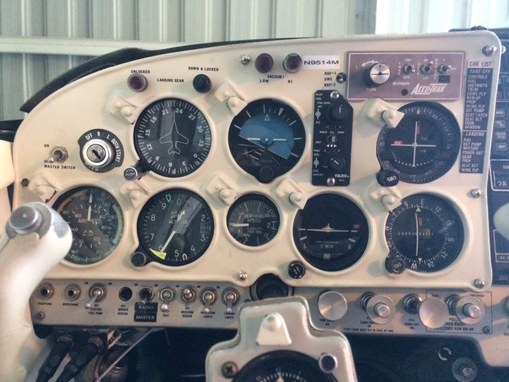
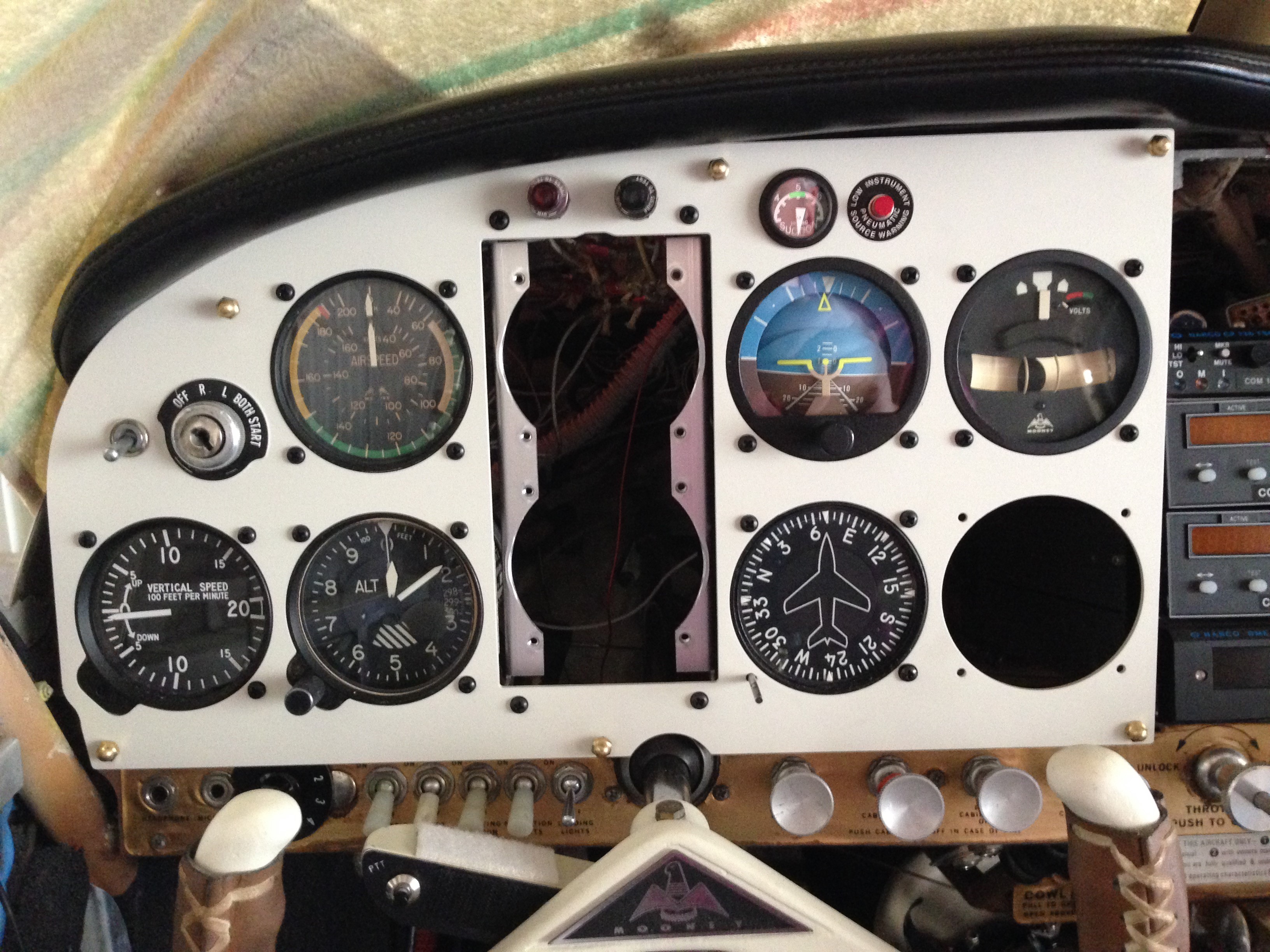
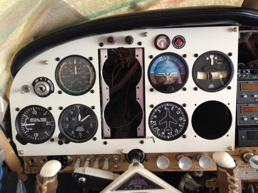
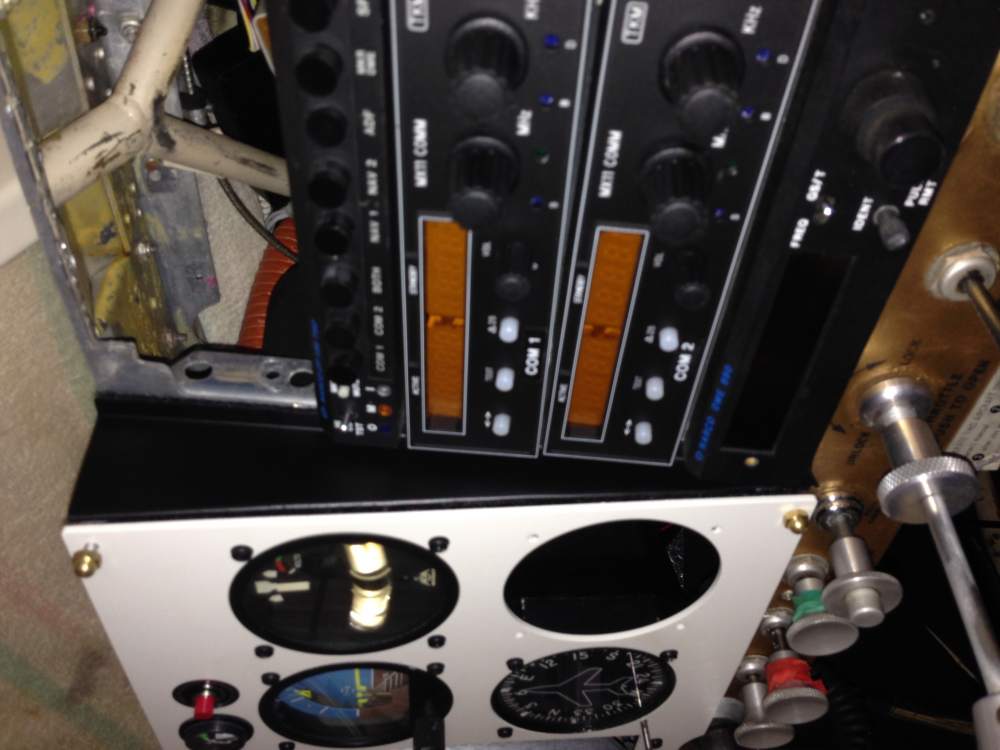
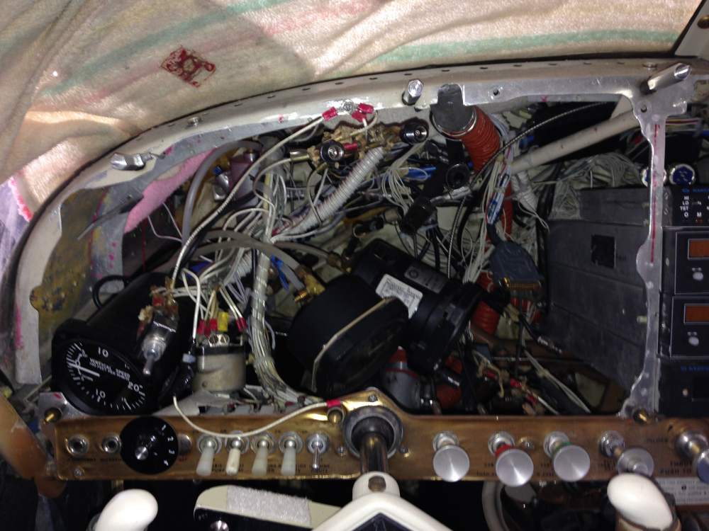
I had been surfing for some professional looking labels but hadn't settled on anything yet. It'll be the plain old label maker for now. See pics... this is about where I am right now. I'm almost done relocating comm antennas so I can put the Aspen RSM and GPS antenna where the comm antennas used to be. We'll get there...
-
Thomas,
As for labeling, years ago, after I refinished old plastic overlay I used Dray Transfer Panel labels like these:
http://www.aircraftspruce.com/catalog/cspages/panelmarkset.php?clickkey=5006843
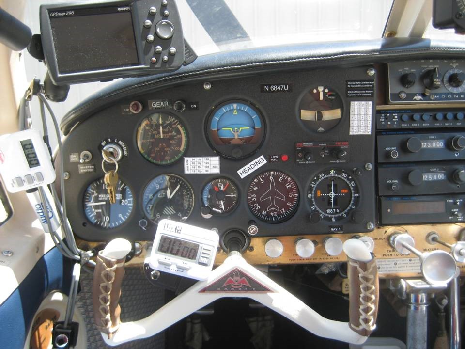
It turned out quite well but I had to clear coat the panel overlays to protect from rubbing. You can see the picture here.
Regards,