

Flynic3
-
Posts
9 -
Joined
-
Last visited
Flynic3's Achievements
")


-
M20M Bravo ASSS Issue, not preventing Gear Retraction
Flynic3 replied to Flynic3's topic in Modern Mooney Discussion
Good Afternoon, I wanted to post a follow up to my previous posts after further diagnosing the ASSS in this M20M Bravo. We found the ASSS to in fact be faulty and the easiest way to do this is relatively simple. The VeP 654-34 is essentially a diaphragm with two microswitches and the easiest way to diagnose whether the ASSS is faulty is by checking Continuity between the blue wire (Pin #2) and red wire (Pin #3). If you have continuity between these wires without 65knots than the ASSS is faulty. You should normally have continuity between the white wire (Pin #1) and red wire (Pin #3) when you are on the ground and airspeed hasn't reached 65 knots. It is as simple as that, and after chasing the rabbit down the hole further than I would have liked to, I realized I was over complicating things. I hope this may help another Mooney owner who has experienced this issue with the gear coming up without the adequate airspeed. I am curious why a simple pressure transducer wasn't used instead, as it seems this would be a much more reliable system compared to the Diaphragm and microswitch arrangement. Regardless, I just wanted to provide further insight into the ASSS and hope it saves someone the hassle in the future. Cheers! Nic -
Flynic3 changed their profile photo
-
Good Morning, I am not trying to flame any fires here but couldn't help but responding to a few comments posted in regards to G1000 equipped aircraft. I just wanted to break things down a bit for the OP to consider about arguments made for and against. I am not a Mooney owner, however install Avionics for a Part 145 repair station, and my statements are based on my experiences with repairing and servicing G1000 aircraft. I think the biggest weakness of the G1000 is three fold... 1. The G1000 is STC'd to the Airframe so you are basically stuck with the G1000 unless you remove it completely, which would require a major alteration approval... in the UK may be a difficult task. 2. The G1000 was the first Garmin EFIS certified, and in my opinion they locked themselves inside a tight box to pass certification when it comes to software, configuration etc... furthermore the Software level and features are controlled by the Airframe OEM's as well. 3. The GIA-63W's required for the WAAS upgrade are no longer manufactured and extremely hard to acquire, so if the Aircraft has not been upgraded yet... again you are stuck. The WAAS upgrade typically runs $32-36K, and for the money spent you are getting fairly minimal bang for your buck... more or less just bringing things to a 2008 standard. I typically see a lot more failures on the G1000 components and the cost to repair or receive a newly overhauled component is more expensive. With all the knobs and buttons on the G1000 display, something as simple as a rotary knob failing will cost you $3k+ plus 6-8 hours of labor. I have replaced 4-5 Displays in the last year for this reason, and also see a lot of GMU-44 magnetometer failures on older systems. I have come across a few failures of other LRU's like the GRS-77 AHRS and GDC-74 ADC, but those two issue's stand out as more commonplace. The repair and replacement of the G1000 components are also a bit more labor intensive as well, mostly due to the time it takes to reload software and configuration settings etc. Even a simple software update can take 4-8X longer compared with newer EFIS systems depending on options installed in the aircraft, so again is much more labor intensive compared with newer systems. I have spent as long as 12 hours reloading software into a G1000 equipped Cirrus SR-22... which is ridiculous. As a general rule of thumb, the G1000 can be a nightmare when it comes to upgrades and servicing... especially when compared to newer EFIS systems. That all being said, from a pilots point of view the G1000 is still a great EFIS system overall, especially when equipped with WAAS, GFC-700, SVT and GTX-345R. This is a great IFR combination for most, but once time passes another 10-20 years, I will be interested to see what upgrade paths will be available for Mooney owners. Compared with the newer G3X and G500/600TXi EFIS systems offered from Garmin, the G1000 is definitely showing it's age. You can't buy into an older EFIS architecture expecting to get comparable features and reliability of the more modern EFIS systems. The NXi upgrade is mostly CPU and better Displays due to the G1000 hitting a point where they could no longer add additional features without experiencing noticeable delay in panning of the moving map etc. This was also the case with the GTN series as well and why the Xi's offered the same CPU/Display upgrade... the original GTN's are only 10-11 years old, so stating a non-WAAS G1000 is modern would be misleading. They are still a decent system to fly behind, but if I were looking at purchasing an Ovation like the OP... I think I would lean towards purchasing one with a standard six pack, myself. This leaves you with a lot more upgrade options, and I would lean towards installing a G3X or G500Txi over buying a G1000 equipped Mooney. In doing a quick search comparing GX Ovations versus similar airframe time models from the late 90's, you save $100K or more... which would buy a much more modern and capable Glass panel. This again, is just my personal opinion based on my experiences with servicing G1000 equipped aircraft. I hope this helps... Nic
-
M20M Bravo ASSS Issue, not preventing Gear Retraction
Flynic3 replied to Flynic3's topic in Modern Mooney Discussion
Good Afternoon, After further diagnosing this issue we have found that all of the Red, White and Blue wiring coming from the ASSS match the schematics and has continuity... the leads are also pinned to the correctly labeled A/S# 1 CPC and corresponding wire labels are also correct. I am moving further downstream to the Gear control CPC to check continuity going to the A/S#1 CPC. I have not found anything to indicate a wiring issue thus far, and everything matches the Mooney Schematic but the Yellow, Black and Green wire leads. I was curious if anyone has ran into issue's with the ASSS Bypass switch constantly overriding the output from the airspeed switch. I am more or less wanting to determine if there could be any other root causes beyond just a faulty ASSS. I just do not want to spend $1,400 and wait a month to receive a new ASSS, only to find out that it was not the Airspeed switch. What would be the best way to diagnose whether the ASSS itself is faulty? I spoke with the guys at World Magnetics and their VeP engineer stated that I just need to verify the wiring leads matched the schematic and were connected to the correct wiring labels from the CPC. I would just prefer to be a bit more thorough in the diagnosing of the ASSS, prior to telling the customer we need to replace it. I would love to know if anyone has ran into other issue's with this system, beyond a faulty ASSS... and whether the ASSS is usually the culprit. I greatly appreciate any insight and assistance you may have in this matter! Cheers, Nic -
M20M Bravo ASSS Issue, not preventing Gear Retraction
Flynic3 replied to Flynic3's topic in Modern Mooney Discussion
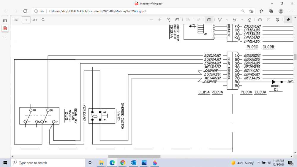
Attached below is the ASSS portion of the Schematic that I was referencing in my original post... which leaves a lot to be desired when it comes to the Yellow, Black and Green portion of the ASSS circuit. It appears as though the Red, White and Blue side of the ASSS Circuit is going to the Gear Control CPC Pins 3,5,7 from Pins 3,2,1 on A/S#1 CPC. I just wanted to post additional information about this aspect in case it would assist another Mooney owner in the future. I read quite a few threads about this issue, and thought it may provide further detail for future use. That being said, I have noticed a lot of differences on the schematics based on the serial number... when it comes to wiring and CPC labeling... so it may only be viable for the specific serial number range that I am working with currently. The overall systems seem to be similar though, so it may at least provide a decent base line... and I hope it will help! Best Regards, Nic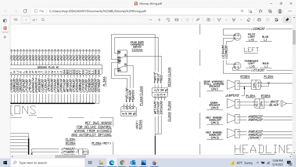
-
M20M Bravo ASSS Issue, not preventing Gear Retraction
Flynic3 replied to Flynic3's topic in Modern Mooney Discussion
Good Morning Skip, I greatly appreciate the quick reply and for the insight provided in your post... it is greatly appreciated. I will further diagnose the Red, White and Blue side of the ASSS circuit to determine if we have a bad switch, or a wiring issue. When I saw the way the Yellow, Black and Green side of the ASSS circuit was altered, I assumed this may be our problem. I would still prefer to have things repaired to what the Mooney factory schematics specify to prevent future issue's. That being said, based on your comments above I will focus on diagnosing the Red, White and Blue portion of the circuit along with the ASSS itself. It does appear that this portion of the ASSS has not been altered and is intact. If it does come down to replacing the ASSS, it appears as though this is a bit of a challenge as well... but will cross that bridge once we get there. Thanks again for all your insight and assistance... I truly appreciate it! PS. The Schematic for this particular M20M is 800304 Rev. AA... Serial 27-0232 thru 27-0239 and I have attached it below. Best Regards, Nic Mooney Wiring.pdf -
Good Afternoon, I have an M20M Bravo in our shop finalizing an Avionics install and annual inspection. During the landing gear testing sequence we experienced gear retraction even when airspeed was less than 60knots indicated, and even when at zero airspeed. During further inspection of the ASSS we found that A/S#2 CPC connector was missing, and replaced with a 2 pin molex, along with the Yellow wire lead being capped and stowed. It seems as if this portion of the ASSS has been incorrectly altered and essentially disabling this system to prevent gear retractions while on the ground. I am attempting to correct this issue but having a devil of a time with tracking down what needs to be connected to the Yellow wire lead. The full electrical schematics does not specify the wire label connecting to what should be Pin #2 of A/S#2 CPC. This lead is connected to the NO portion of the relay with the Yellow, Green and Black wires. It also looks like the NC portion of this relay is connected to ground when the Green wire should be. The main Electrical Schematic references RC04A however when digging deeper, I am still not finding adequate leads on what this portion of the ASSS needs to be connected to. This Mooney has the gear safety bypass switch, so I am really not understanding why the ASSS was altered in this manor... I was curious if anyone had better wiring schematics for this specific ASSS system, as I have not had much luck with finding one. It does appear as though AS#1 CPC is intact and was not messed with... the 3 wire bundle with the Red, White and Blue leads. I did find a schematic for a different serial number range showing the Yellow wire lead connected to DM06A20 which I think is the output signal wire from the Hobbs. That being said, the schematic for my specific serial number does not give that information. I would assume that I will need to recreate AS#2 CPC with the Yellow wire connected to the correct wire lead along with the Black wire and switch the ground to the Green wire instead of the Black. I just could really use some guidance of the wire labels connected to Yellow and Black wires of the ASSS. If anyone has better knowledge of the ASSS system, it would be greatly appreciated!
-
Good Morning, I greatly appreciate the response Aerodon... I recommended the GI-275's and feel this this would be the better choice as well. That being said, the customer is adamant that they would like to stick with the G5's in order to have the same setup as their other aircraft. I will send along some photo's of the panel shortly... and I greatly appreciate your assistance in this matter! Warm Regards, Nic
-
Good Afternoon Gentleman, I apologize up front for reviving an older thread, but was curious AeroDon if your recessed flushmount brackets would work to replace a KI-256/525 AI and HSI Combo on the M20M Bravo? It looks like it may require cutting out a portion of the panel to allow for the G5's to be fully recessed. Your flush mount kits seems to be the best I have seen offered, and I was just curious if we could customize it a bit to for this installation. I figured if I attached the four corners and cut out the spacing between the KI-256 and 525, it would allow for a perfectly recessed pair of G5's. The included brackets with the G5 kit would actually leave a slight gap on either side of the G5, and that is mostly why I decided to go the flush mount route for this installation. I am sure there are other mooney's out there with this existing combination who would also be interested. I would be willing to provide any pictures you may need if that would help... Cheers! Nic
-
Good Afternoon Gentleman, I apologize upfront for reviving an old thread, however I am attempting to find a wiring diagram or schematic for an M20M Bravo's Avionics (S/N: 0234). I have the ATP wiring schematic which gives an overall diagram of the electrical systems however does not include much on the Avionics side of things. At this point all I have to work with is pinouts and shrewd Bendix King schematics for most of the Center Stack. This M20M Bravo in particular has a Bendix King KMA-24, KLN-89, KX-165/155 Combo for NAV/COM 1-2, KFC-150, KT-76C, WX-1000/SKY496 StormScope and Traffic, EGPWS etc. I am not even sure if anyone has ran across such an avionics specific wiring schematic for this series of Mooney, but I am not having much luck on my end. Working on a major avionics upgrade and would love to get a better idea of what I am working with prior to tearing into things. I greatly appreciate any help, and greatly appreciate your time! Best Regards, Nic


