brndiar
-
Posts
168 -
Joined
-
Last visited
Content Type
Profiles
Forums
Blogs
Gallery
Downloads
Media Demo
Events
Everything posted by brndiar
-
Gyroscopic Effect (gyroscopic precession): ...Whenn axis of a propeller (gyroscope) is pitched or yawed, the force induced into propeller is precessed and returned to the airframe at 90 degree form original direction in the direction of rotation, which practically means that: - if your input is a pitching motion, you get back a yaw effect -if your input is a yawing motion, you get back a pitch effect Our MOONEYS have relatively small propellers, the forces are not great and the effects are seldom noticed. Effect has practiacall application in flying aerobatics figures. For an ordinary pilot (according to me) is gyto effect relevant in slow flight and high power scenarios with abrupt pitch or yaw inputs. Example (Lycoming): suddenly & energically pushing yoke close to stall speed (critical AoA) with the engine at high power you get a yaw to the left, wich could be a left spin entry..... By spinning to the left and full power there is pitching up effect, which leads to flattening of the spin... Lifting the tail (taildragger wiht Lycoming) in the start phase causes momentary extra yawing (turning) moment to the left, extra right rudder is required.... P.s. do not understand how is the above picture related to gyro effect. Lg, M PPL only, Aerobatics rating
-
Hi, .....we are flying behind Lycomings.... Engine& Prop. turns Clockwise (as viewed from Cabin).....it causes "rolling force" that pushes LEFT wing (wheel) down.....(Newton).... .... to correct that more lift at left wing is needed, it means right aileron (ev. Aileron Trimming to the right)... ....The aerodynamic center of the vertical tail is above the aircraft roll axis and so the force generated by rudder deflection does produce a rolling moment... correct, BUT the right rudder that is needed in that situation produce rolling moment in the SAME DIRECTION as ROLLING MOMENT CAUSED BY TORQUE (High power setting), to the left (this force would be probably negligible). .... NO.... right rudder, that is needed to counteract P-Factor and Slipstream in these situations DOES NOT COUNTERACTS TORQUE (in that case TO THE LEFT) (flying slow, high AoA).... Torque is the only force that "rolls" and no "yaws" or ev. "pitches" the plane and is corrected by use of aileron (different lift). ...Of Course you can cause "roll" moment to the right by momentarily applying right pedal and like this momentarily increasing lift of the left wing.... LG, M P.S. PPL Only, Acro rating.
-
To be correct, the right rudder counteracts spiraling slipstream and P-Factor effects, but not torque. Torque, in contrast to Slipstream, P-Factor and gyro effect does not "yaws" but "rolls" the airplane and "per se" is corrected (in air) with aileron use. LG, m
-

Fuel Gauge Troubleshooting Tips Please
brndiar replied to brndiar's topic in Vintage Mooneys (pre-J models)
Thanks you for Tips. Checked Mooney Parts Catalog (rev. June 1977). Does the late M20C have an Inboard Fuel Senders only ? (Part Number 610242-001). Outboard Fuel Senders (No 15 in Catalog, Picture C) are related to F model, but not to C model ? That s how I understood the Catalog. At the time I would like to replace not working sender only and keep the stock gauges. There some units to find at aftermarket. Does someone to know, If Ceis sending units can be used with the stock gauges? Has anyone done this? Was reading through their install manuals and it looks like the gauges with resistive analog outputs and with digital outputs are two different parts. Digital Gauges with Engine monitor will be my next Project. m.jpg.34bff965170047385ce092ef7a294092.jpg)


.jpg.6f2eada9c2110bc3b3c5da7f503c1a4a.jpg)
-
Fuel Gauge Troubleshooting Tips Please
brndiar replied to brndiar's topic in Vintage Mooneys (pre-J models)
Where can I buy (or let overhaul it) the analog, resistor-based inboard fuel sender for my 1977 C Mooney? Thanks -
Fuel Gauge Troubleshooting Tips Please
brndiar replied to brndiar's topic in Vintage Mooneys (pre-J models)
Thanks, How can I do it practically here?
-
In my 1977 C with "J" Instument Cluster the Right Fuel Gauge sometimes reads 0 (Empty). Sometimes, in flight, or after landing reads correctly again. When it works, it reads correcty the rest of the day, even after refueling and master switch cycling. But after some time in hangar is again "dead". The plane is always hangared with full tanks. The respective tank was resealed receantly, but I do not suppose "mechanical" problem with Swimmer, because If I remember correcty, the problem was sporadic even before resealig. Last Time I tryed to shake wing, without succes. Any tips for trobleshooting? Thanks in advance, milos
-
Prop Strike due to partial gear collapse
brndiar replied to Urs_Wildermuth's topic in Mooney Safety & Accident Discussion
Hi, The same problem. I Started a Thread, back in 2020, your reply is in that Thread (Screenshoot below). 75 dBA was a result that was achived with a different noice mesuring system (old one). From Hartzell I got a link to EASA database https://www.easa.europa.eu/domains/environment/easa-certification-noise-levels and explanation: "Whatever the reason, for the listings in the EASA noise level archives, you can bet that we had nothing to do with it. Here’s what I can tell you about it Prior to 1988 noise was measured at 1000’ AGL (overflight). In FAA speak, this was FAR 36, Appendix G. EASA, or more specifically the Authorities that preceded EASA called in ICAO Annex 16, Chapter 6. After 1988 both organizations changed to a noise measuring system that took take-off and climb performance into account. The better a plane climbed, the higher it would be at 8200’ from where the airplane started rolling, and the microphone is set up. This Take-off method is called FAR 36, appendix G, or ICAO Annex 16, Chapter 10. I can tell you that Hartzell never tested a M20C with any prop on it for the FAA or EASA. Both of these prop TC/STC’s were validated in Europe well before EASA was established. Hence they were grand-fathered in without any noise testing on our part. The note that EASA has pertaining to the three blade entry is “”9/24/201 Engine designation revised”. Looking at the numbers themselves, the Chapter 6 numbers are on props that were TC’ed. Maybe these numbers came from Mooney from the TC process? I can only guess. The 7282 three blade is approved on an older STC. In 2010 we added eligibility for the Powerflow exhaust to the STC. The only thing I can think of is that when Powerflow applied to validate their STC it must have initiated some noise discussion. If you will note, 85.5 dB(a) is the maximum allowable under Chapter 10. That seems like allot for un untested unit that is the same diameter as the two blade?? So, to get to the bottom of your questions, The props are the same diameter. They should be about the same noise-wise, except the 3 blade climbs better (CHAPTER 10). The numbers in the archive compare two 74” props at the same RPM, using two different methods, one of which may be considerably closer to the mic, and the Chapter 10 listing is as high as it can be to pass. It seems almost arbitrary?? The three blade certainly is not 10 dB(a) louder than the two blade." lg, m
-
Thanks for explanation. Found it as a Headline in the Czech Aeroweb server. https://www.aeroweb.cz/ lg,m
-
https://www.bizquest.com/business-for-sale/legendary-aircraft-manufacturer/BW1902593/
-
brilliant evaluation
-
too much "free movements" of rudder Pedals by taxing
brndiar replied to brndiar's topic in Vintage Mooneys (pre-J models)
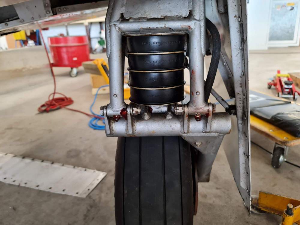
I let the shop to check again bearings and rod ends. Thanks for SB20-20. I do not unterstand Instruction Nr. 4: "IF AXLE POSITION, FORWARD OF PLUM LINE, EXCEEDS .06. ???? (0,6 INCH?) First picture below - taken from left (Left Edge of the picture is front). Mmike20papa20, M20Doc, Simpson77, all you where right, there are two loose bolts in the steering horn, simply worn nose gear parts. Time for a horn rebuild..... My Bottom line: with Donuts replacement (my were 40+ years old) it is very practical to have nose gear parts exactly checked, because: 1, save second visit of the shop. 2, you avoid "rodeo ride" instead of expected smooth landing (I exaggerated here a little :-))))) ). LG aus Austria, Milos

-
too much "free movements" of rudder Pedals by taxing
brndiar replied to brndiar's topic in Vintage Mooneys (pre-J models)
Thanks for tips. Below video. There is cca 0,8 inch free movement of the rudder, free movement of rudder Pedals cca 0,5 inch, but NO free movement in the nose wheel linkages. lg, M -
too much "free movements" of rudder Pedals by taxing
brndiar replied to brndiar's topic in Vintage Mooneys (pre-J models)
link? thanks in advance lg, m -
Hi folks, Just got my bird from annual. Among other things, the Donuts were replaced. By first 2 landing after annual I noticed "S" curves during landing roll (crosswind situation). I assumed error in my Landing technique. Thereafter by taxing I noticed cca 1-2cm of free movement of rudder Pedals for the first time. In my past 200+ hours I did not noticed that problem. On ground there is cca 0,5 cm free movement of rudder too. How huch is tolerance? Any ideas? Thanks in advance. Milos
-
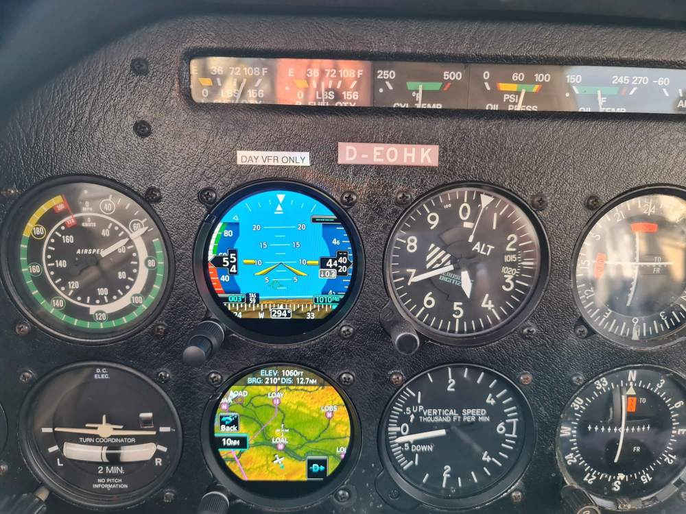
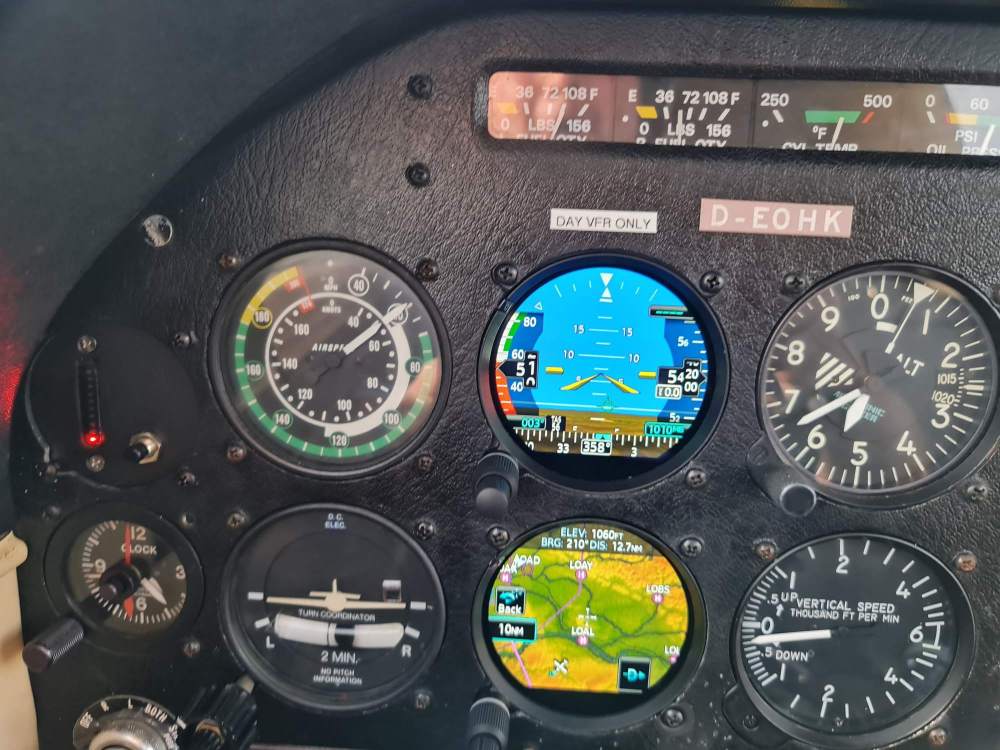
Stall speeds according to POH (1977, M20C) 1, clean 58 knots 2, Flaps TO+gear down 56 knots 3, Full Flaps + gear down 49 knots. Practically (tested yesterday- Weight 1017 kg, CoG 1188 mm, power off) Pictures below 1: clean 2: TO Flaps+ gear down 3: Full Flaps + gear down lg,m
-
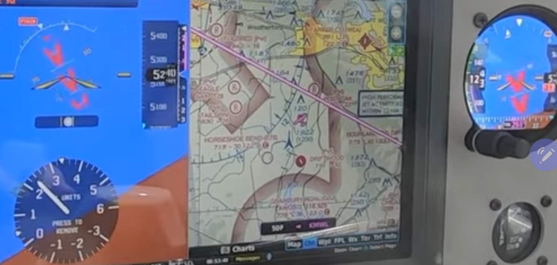
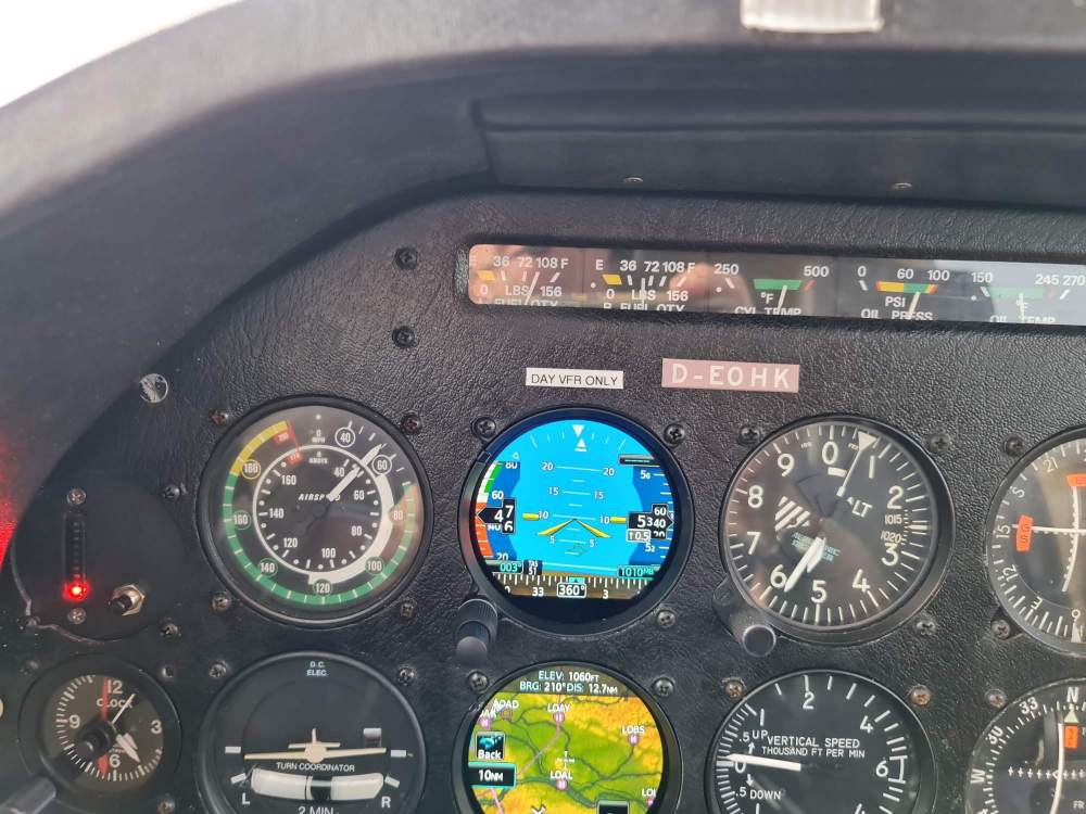
FOR AVIONICS UPGRADE TO "GLASS COCKPIT" from "STEAM INSTRUMENTS" THERE IS ONE IMPORTANT THINK TO POINT OUT: There is a Phenomena known as "Roll reversal errors (steering the wrong way, i.e. making a bank angle steeper rather than recovering from it) which have been known to contribute to many loss of control accidents in aviation. There are 3 Formats of "SKY POINTER and Roll index" in "GLASS COCKPITS" nowadays: 1, General Aviation (GA): roll index slaved to the aircraft symbol and located on the top of the AI. 2, Commercial: roll index slaved to the moving horizon. 3, Military: roll index slaved to the moving horizon but located on the bottom of the AI (the "sky pointer" is really an "earth pointer"). It seems to me, that "Commercial format" dominates Glass cockpit avionics replacing steam instruments in our GA fleet. I as a GA pilot I am used to GA format where Lower Triangle is "SKY POINTER", Upper Triangle (with roll index) is "the CASE" and is connected to seat as well as to the aircraft symbol, IT DOES NOT MOVE. Logically, during recovery there is need to move lift vector (generated by our wings) toward the sky the shortest way. For recovery from a right bank (reference GA Format), the pilot moves the stick, and the roll index ("THE CASE", THE UPPER TRIANGLE) intuitively to the left. Analogically is it in the pitch axis: a forward movement of the stick moves aircraft symbol down and vice versa. It meas in GA Format the ROLL INDEX AND CONTROL MOVEMENTS ARE ALWAYS IN HARMONY. On the contrary with Roll Index slaved to Horizon (Commercial format) recovery from a bank requires the Stick TO BE MOVED IN A DIRECTION TO WHERE the roll index will go. In one study was found that the commercial format (roll index on top of the AI, slaved to the horizon) was almost five times more likely to produce roll reversal errors than the military or general aviation configuration. Be aware, what and where your "SKY POINTER" is. At the Picture below Left Commercial Format, Right GA Format at right bank and the nose too high: required is stick to the left + forward) Lg, PPL only, no CFI. m

-
+20 year old donuts (1966 M20E)
brndiar replied to Matt Ward's topic in Vintage Mooneys (pre-J models)
44 !!!! Years old Donuts go to retirement. Despite their senior age, they always served well .... lg,m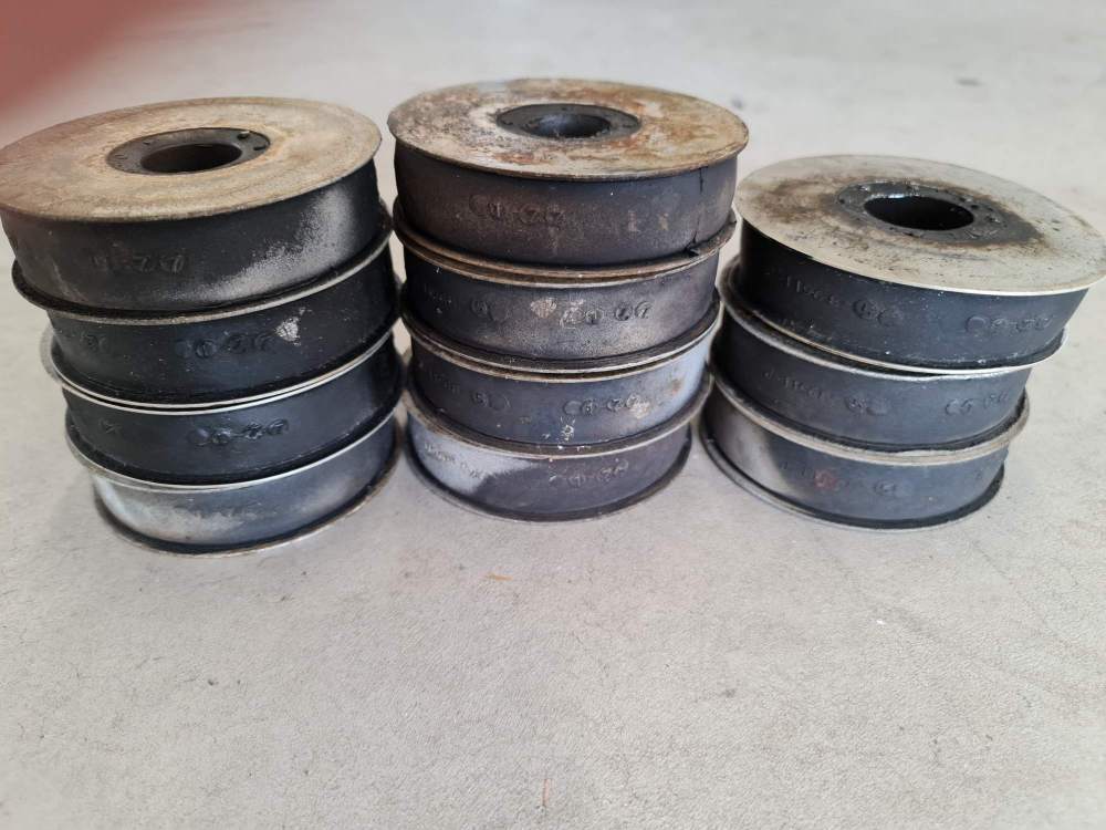
-
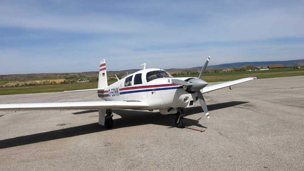
My Project with 2×G275 (1977 M20C) lg,m

-
Hi. Everyone find answer in this video: Lg, Milos
-
I would like to mention here a simple technique that I found on net. It is very interesting, it use concept of "longitudinal flare cut-off point". After tried myself, I must say, that it is simple, and applicable practically in any case. Need to say, that before practicing with my Mooney I did few dozen landing on a sim, just to get used on required "visual references & perspective" (I mean I did not to train "muscle memory" for stick and rudder skills) My video using this concept is here: https://www.youtube.com/watch?v=MwCIZkq_xqQ Please consider It is the second practical landing using the concept - have to tune some details. At first I did not have a camera on board :-))). For complete theoretical material a purchase of app. was needed for app. 38E. Concept & Technik here: : https://www.jacobsonflare.com/ Subjectively, I must say that these were some of the best money invested in my flying. lg, M. P.S. PP ony, no CFI, I do not have any economic profit.
-
Hi, Please, what is technically need (to buy) for moving the Battery to behind the rear seat? How much does it (approximately) cost? My is 1977 M20C model, replaced the original old 2 bladed Hartzell HC-C2YK-1BF/F7666A-2 with 3 Bladed Hartzell (HC-C3YR-1RF/F7282), now dynamically balanced. I am happy with it, comparison would not be fair, because engine was overhauled too. Surprise for me was a new Noise Certificate (Thread +Foto) with 85,5 dBA, while in the old one there was 75 dBA (needed here in Europe). As explained to me from Hartzell, this is due to change of the measurement methodology. W&Bs is way fwd so I'm considering in addition to replacing the battery, also moving it back at the next annual (to behind the rear seat). What I need to order for that change? Cost? thanks, lg,m.
-
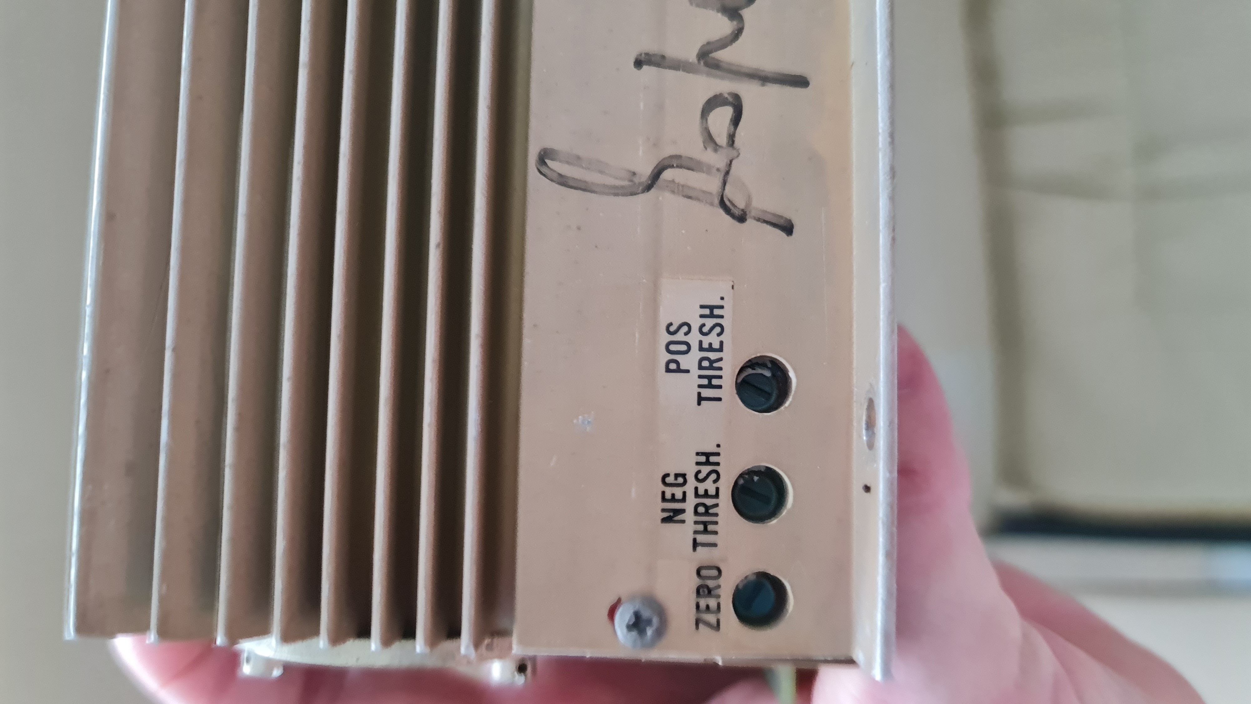
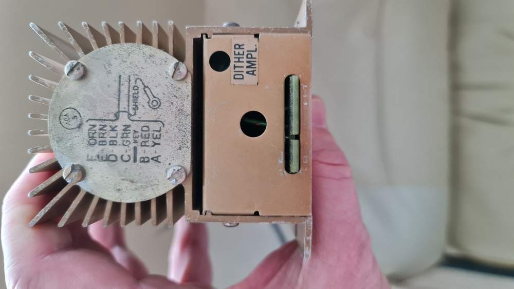
Thank you for your reply. The document in question discusses the setting of "DITHER AMPL", but there is no mention in the document of what affects the potentiometers "Zero, Neg Thesh, Pos thesh" and how to set them. lg,M.

-
My thread to Carb. Idle Mix setting. Carburetor Idle Mixture setting (practically) - Vintage Mooneys (pre-J models) - Mooneyspace.com - A community for Mooney aircraft owners and enthusiasts lg, m
-
Hi, how do you translate "rolls" and "lags" in point #3 & #4 ? Not sure what they mean by that. thanks, m