
Kevin Harberg
-
Posts
100 -
Joined
-
Last visited
Recent Profile Visitors
2,653 profile views


Kevin Harberg's Achievements
")


-
C-GXTR FOR SALE.pdf
-
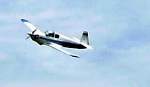
Happy New Year! Here's another video of C-GXTR that was placed elsewhere in the forum regarding the exhaust note of the CA-65 powered M-18.
-
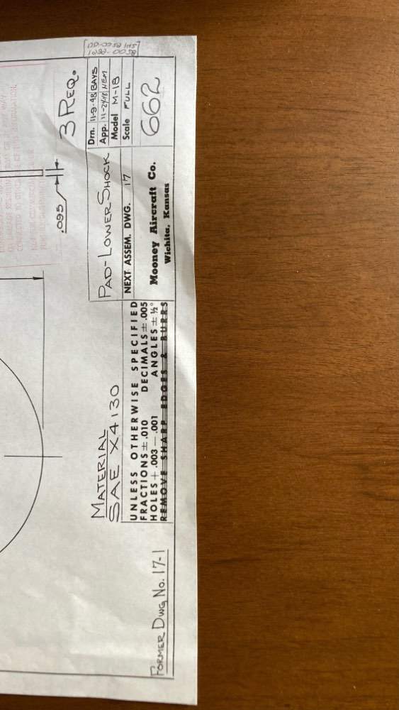
Happy Thanksgiving Mark, (and to all Mooney enthusiasts). Unfortunately not a positive result from Smithsonian M-18 Lower Shock Pad drawings (for scaling replacement donuts). The drawing received is for the thin metal plate that separates the pucks. Can't seem to find any drawings related directly to the rubber components.
-
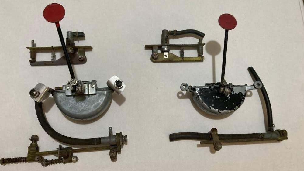
Wig Wag Gear Indicators Mooney M-18 The Wig Wag on the left is made by: The Wig Wag on the right is made by: The Anderson Co. Gary, Ind TRICO ANCO (Maxi Vac Model MV 1B) ¼” hose fitting 3/16” hose fitting One of these units is likely off of my M-18LA serial number 142 and the other is likely off of my M-18C serial number 306. Curious if manifold pressure differences between the 145cu in Lycoming (0-145) and the 170cu in Continental (CA65) require different vacuum units or if changes were made on the production line due to availability. My M-18 drawings only show the TRICO unit for both “L” and “C” models. Is anyone familiar with these gear warning indicators? I don’t know which one goes with which airplane.

-
Hi Mark . I have now received the requisition forms and will be sending back to the Smithsonian tomorrow (August 1, 2023). Will DM you with details via Mooney Space.
-
Still no response from the Smithsonian. I provided eMail address, physical address, and phone number for correspondence. I hope they didn't send an untitled eMail (I send those to "Junk" and delete "Junk" on a regular basis. Wish I could discuss purchase with a "real" person via telephone. How I long for the past.
-
Hi Mark @gummirat An application form has been mailed to the Smithsonian and I am awaiting the quote for drawing 0662 (Pad - Lower Shock). This is a bit of a slow process as the Smithsonian only permits mailed-in applications using their approved form, and then they contact the person requesting a copy of the print. The size of the print is negotiated and a quote issued prior to payment transaction. Then they mail the print. Everything done via snail mail. At no time does the Smithsonian review the print to advise if it contains the information desired (I reviewed all available prints a second time to determine if it is the most likely drawing containing the information you require). I am hopeful but not certain that any useful data will ensue.
-
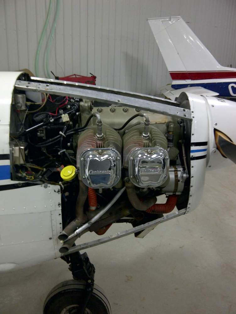
The starboard cylinders suffer the most with heat build up around the exhaust ports. My M18 cylinders look like pictures I have seen of other CA65 powered Mites. I considered purchasing Piper Cub "eyebrows" but just couldn't picture them on a "faster" plane. Many shrouds have been fitted to other Mites to balance cooling. Here is a picture of typical Mite cylinder heat signature.
-
Hello Mark @gummirat I will contact the Smithsonian and check on prints (I expect Firestone has the original drawings for the M18 shock discs), the 1946 design used several outsourced rubber components (including 1942-1959 Chevrolet/GM truck starter pedal boot used on nosewheel steering tube fuselage seals).
-

Mite project for sale in Denver
Kevin Harberg replied to High Plains Drifter's topic in Mooney Mite Owners
All horizontally opposed M18 models built prior to 1953 (and the first half of the 1953 models) had Lycoming 0-145's. Those 65Hp Lycomings had two spark plugs mounted side by side on the top of each cylinder. The Lycoming exhaust exits the left side of the fuselage while the later Continental A65 models had the exhaust exit the right side of the fuselage. Good catch on identifying likely engine model. Twice the displacement of the M18 Lycomings. -
Mite project for sale in Denver
Kevin Harberg replied to High Plains Drifter's topic in Mooney Mite Owners
I agree. -
@gummirat Let me know if I can be of any assistance. I can send you the nosewheel bracket that has the bevelled steel mounting plates if it would be of any use. You may be able to access the aforementioned drawings from the Smithsonian as per my January 11th post. A scan of a "New Old Stock" rubber disc would likely give you the most accurate dimensions. I have some more "used" rubber discs still mounted on a spare set of "Main gear legs" but I suspect they are in similar condition to those I previously provided.
-
Hello Mark @gummirat Would you like me to send you the above piece for cone dimensions? ] Kevin

-
Here's a photo of the metal shock disc mount showing conical shape for top and bottom of each rubber shock disc.
-
The bracket that held the two sample shock discs you received, has a thick conical top and bottom metal disc. The disc between the two shock discs is thin and conical, however, it could have easily been compressed into that shape. Don't know if Clarence @M20Doc has his gear legs apart to verify my findings. Kevin Harberg
