MooneyP87
-
Posts
30 -
Joined
-
Last visited
Content Type
Profiles
Forums
Blogs
Gallery
Downloads
Media Demo
Events
Everything posted by MooneyP87
-

What are your CHT's After LASAR Cowl Installation
MooneyP87 replied to C.J.'s topic in Vintage Mooneys (pre-J models)
Also getting 420-430F right after takeoff on initial climb out, especially when it's hot out. Cruise is around 360-380F depending on power %. Like everyone stated previously, I think you do need to have it checked for the idle/taxi temps as those seem abnormally high, even for a C. -
Thanks! The throttle quadrant I purchased earlier this year from eBay, there's a guy who 3d prints them and sells them as plug-n-play. Hindsight, I should have built it myself because getting it to mount into the rest of the vertical column was a pain and I feel like I could have made them a little more precise, but it's done now. The yokes are honeycomb yokes that I have cut up to pieces and rewired lol. This is all a big learning curve but at some point I plan on making my own to have them more realistic, but these will work for now. All of the switches will be wired up to Arduino boards. There are a few options for the software/switch integration, and I am not certain which one I am going to use yet but once I get to the wiring stage I will make that determination. The reason I state this is, I want to find one solution that I can use for X-Plane and MSFS so that I can test and use both flight sims but haven't had the time to test out different switches, potentiometers, and LEDs.
-
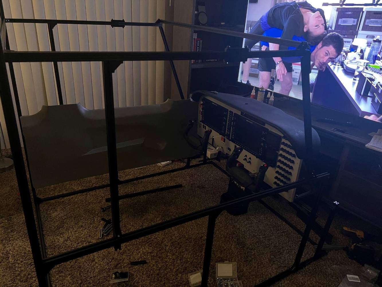
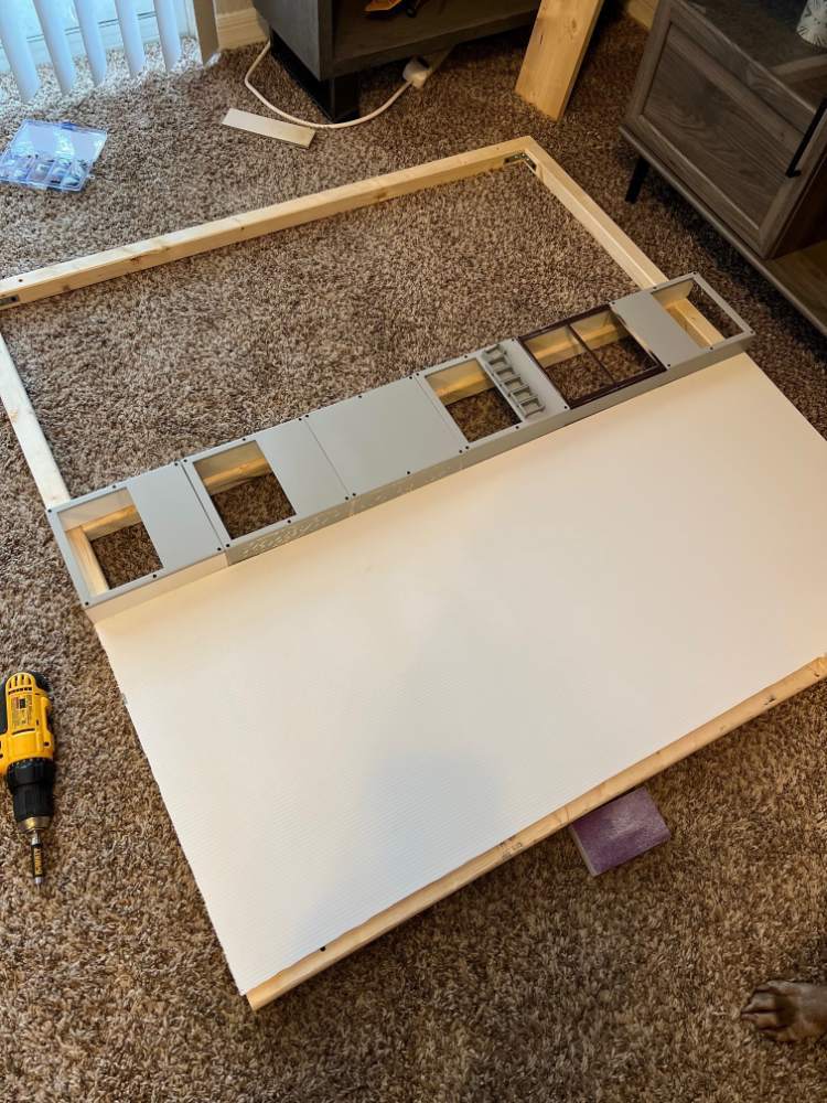
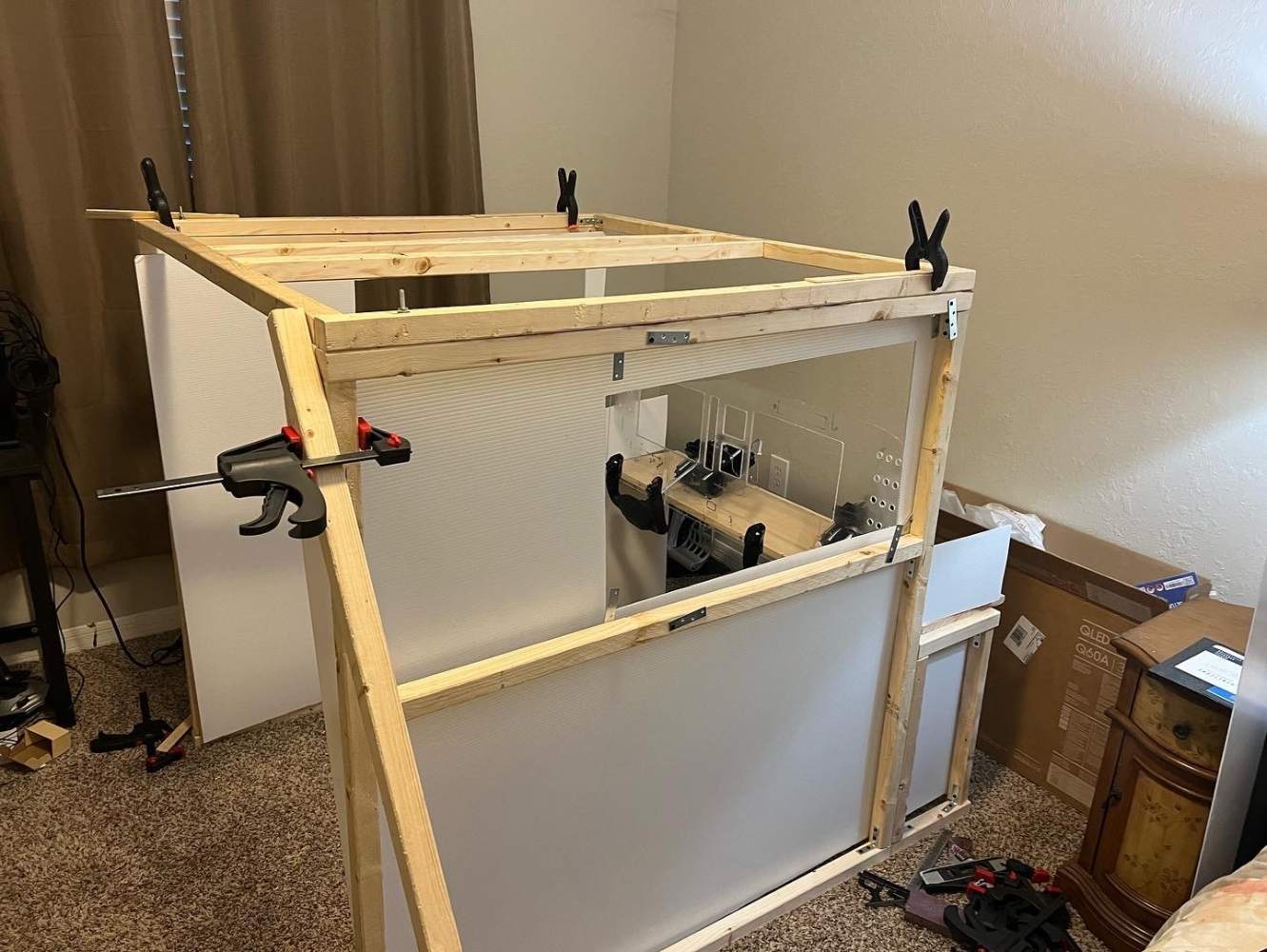
Weekend Update: I have the frame put together and am test fitting the panel and left walls. I still have a lot of work to do but the project is coming along nicely.
-
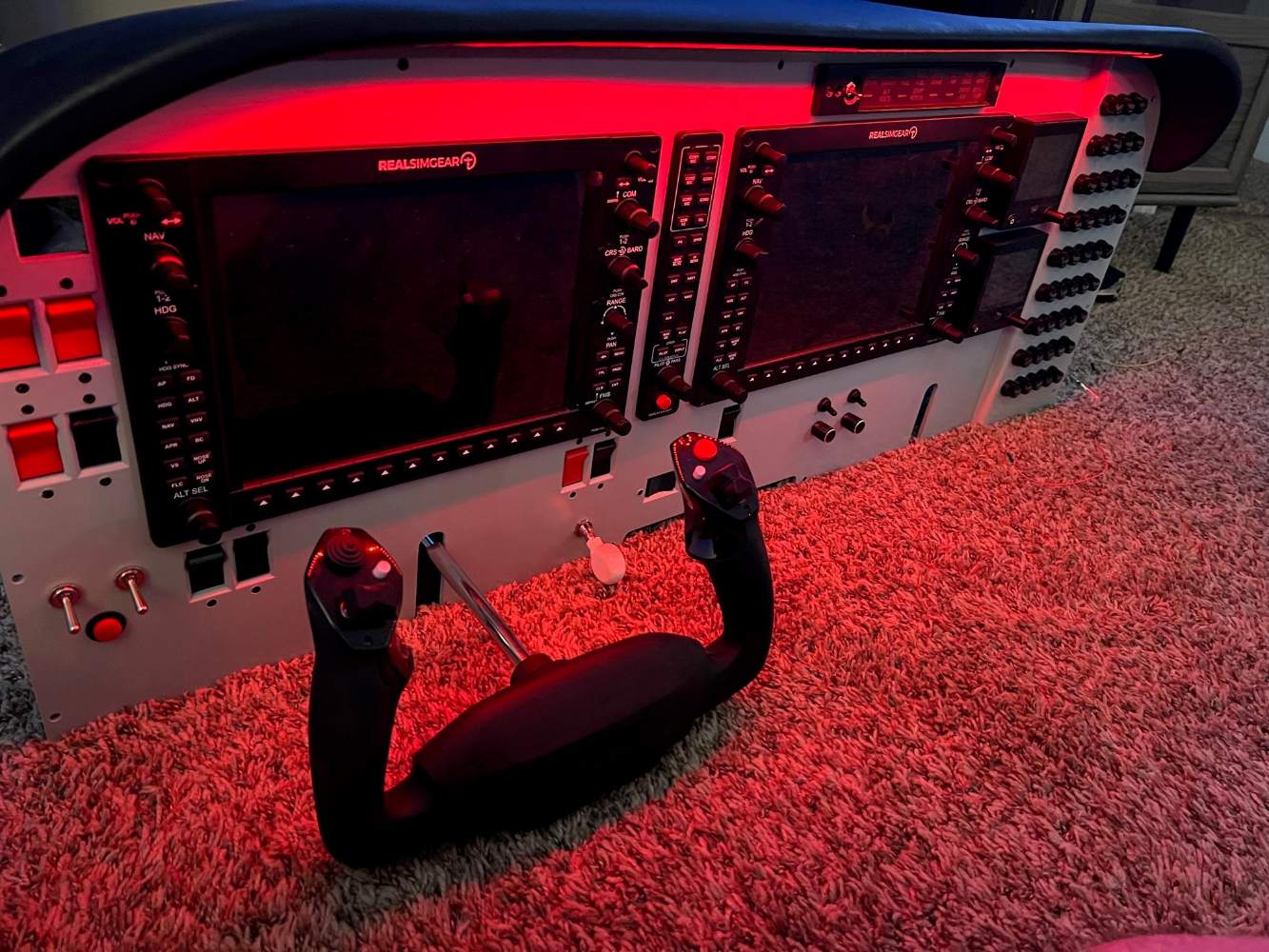
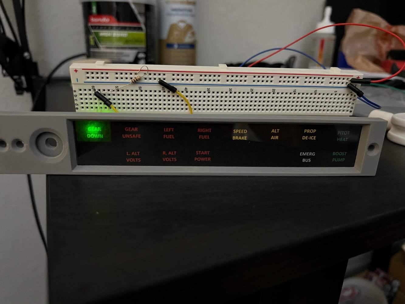
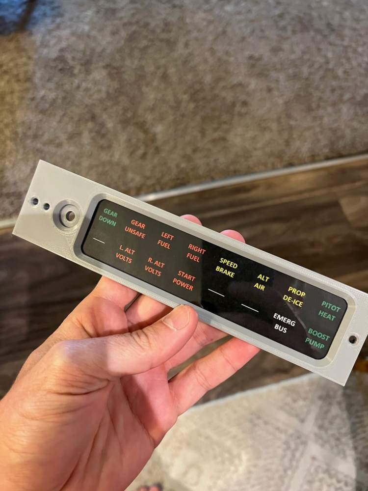
Here's a picture showing the panel with the dash pad attached to it. I've installed and tested the LED lighting strip and I think it will provide adequate lighting, even with the brightness adjusted very low but I won't know for sure until I get everything inside the frame. Now I just need to make the vinyl labels for all buttons and switches and the panel will be ready for wiring.
-
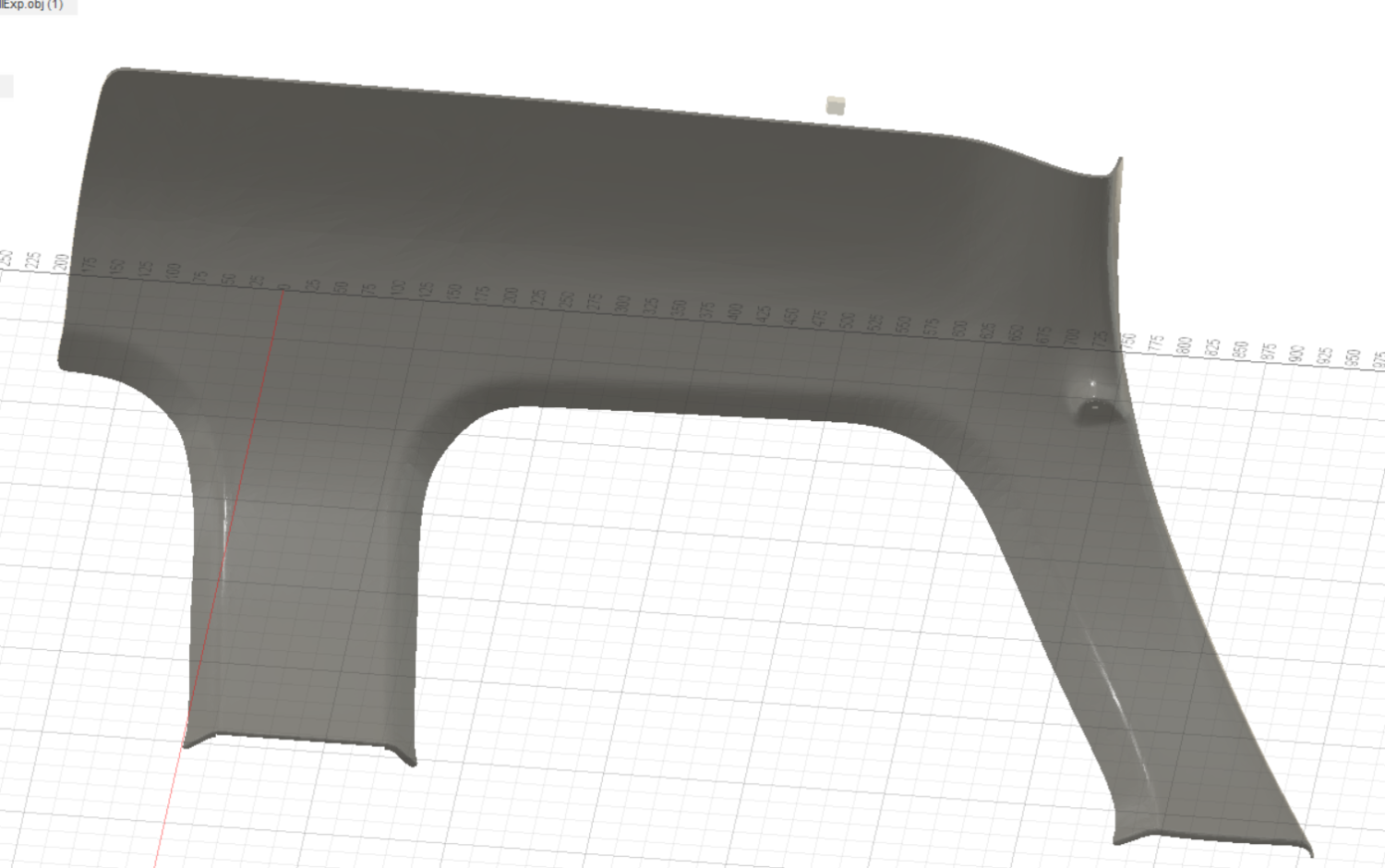
Here's what the pieces actually look like during the process. Picture is the upper left wall I am currently printing. This system seems to be working well for now although I may make a few tweaks to it in the future for additional stability.
-
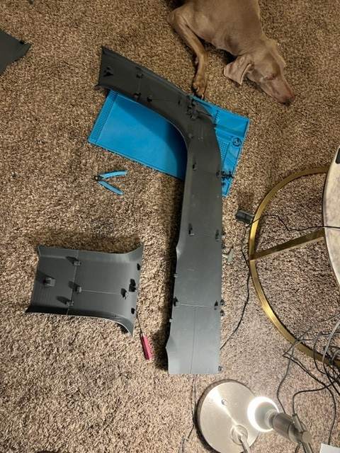
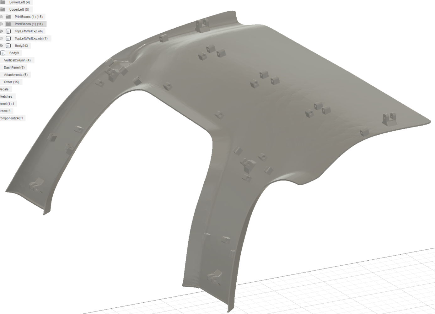
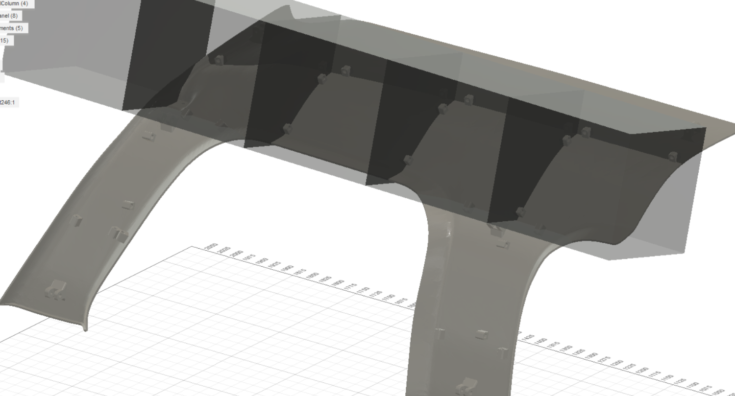
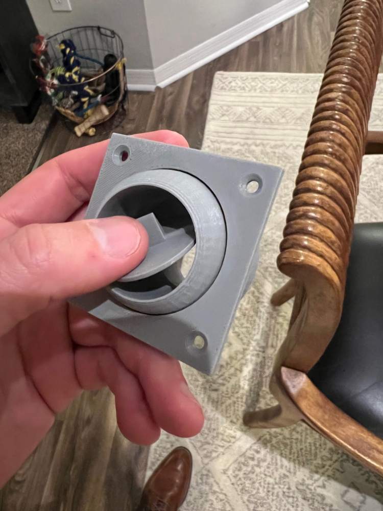
I wish I had a monster printer hiding.. I do have a Prusa XL on pre-order but even once I receive it, it will only print 14" parts; still better than 8-9" though. The answer to the question is the most time consuming part of the project, 3D modeling. I model the main sections and then make cuts every 210-240mm and insert a bracket on the back of the print that will link the parts together with 3mm bolts. See pics for a better explanation. The inside of the cabin looks like one piece, however the rear shows all of the connected brackets that are used when the parts are split so that they can be linked together. The 2nd pic shows the boxes I use to "cut/split" the objects for printing. The large brackets you see on the corners are used to attach the section to the frame of the simulator.
-
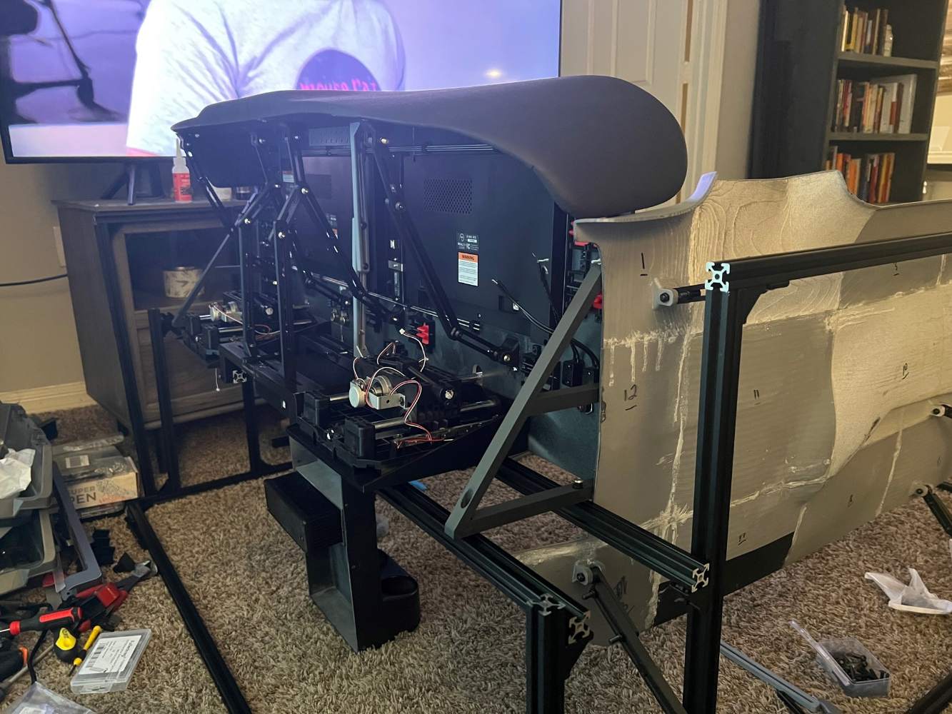
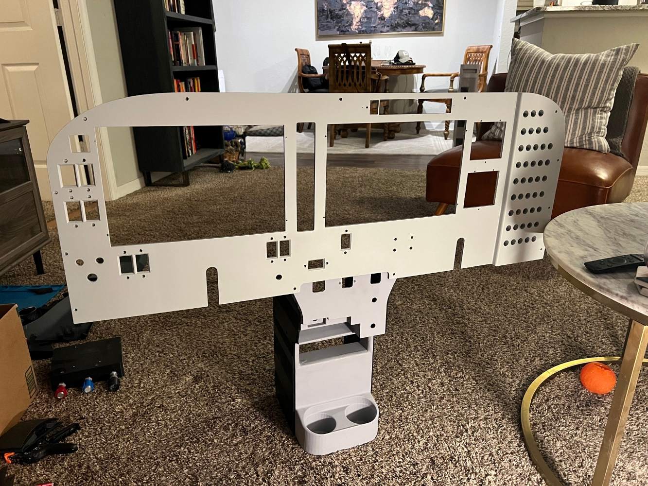
Update post: The panel is painted and ready. I am going to give it a few days to fully cure and then I will install the G1000/G5 units along with the switches. I test fit it with the vertical column last night (2nd pic). I still have some work to do on the vertical column but it is close to being ready for paint. I also finished the dashpad this weekend (1st pic) and finished the left (lower) wall but forgot to take a picture of it. Right now I am printing the left upper wall. Should have some major progress pictures coming soon as I am just over half way finished with the printed parts.
-
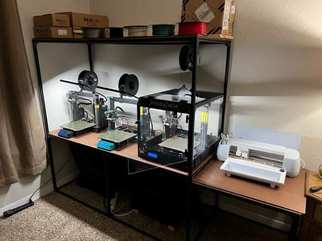
Sure! The three printers shown are all Prusa MK3S's. I also have an Ender printer but I try to not use it unless I need all the printers running as the quality just isn't the same. The parts are extremely durable. For the heavy use parts like the panel, switches, and dashpad I am printing those using PETG with a larger print nozzle than standard with an additional wall layer (typically 3d parts are printed with 2 solid layers for walls but I am using 3). I've tried to break the dashpad with my hands and was unable. The walls/ceiling are printed at 3mm thick with three layer print seams to make them more durable. I have learned that I need to make connector links for all of the large parts so that they can bolt together with 3mm bolts. This isn't so much of a strength issue, but it will help, but more of an alignment correction. Having 18 printed parts for a wall with no way to connect them except some type of glue makes it a pain for linking them together. So each piece moving forward (upper left wall/ceiling, and right sides) will still be large separate pieces but I will make each large section bolt together. This would also allow someone to not be required to glue them.
-
I have no idea what you're talking about
-
Currently doing it for fun however I have had a few people ask if I was planning on selling some type of kit or making it certified. I don't have any plans as of right now to get it certified (however this may change once I have it completed). I have read briefly on the certification process and I would need to provide a plug and play system for this to happen. I could do this but the price would knock most sim enthusiast out. I am thinking about making replica interior kits that would have the framing, walls, ceiling, and possibly a custom panel depending on what the user wants. The panel is where the hard part comes in because not everyone wants a G1000 setup.
-
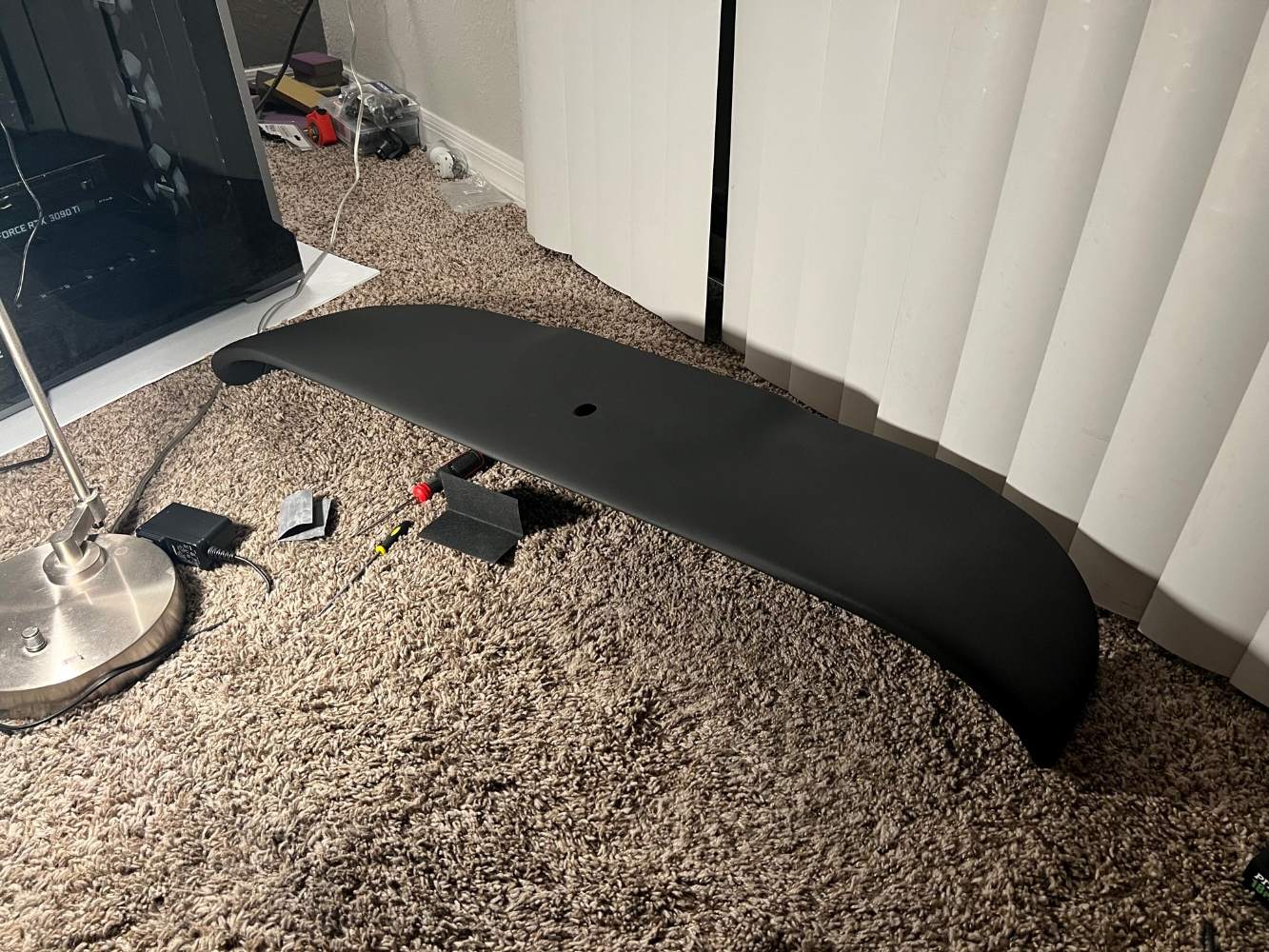
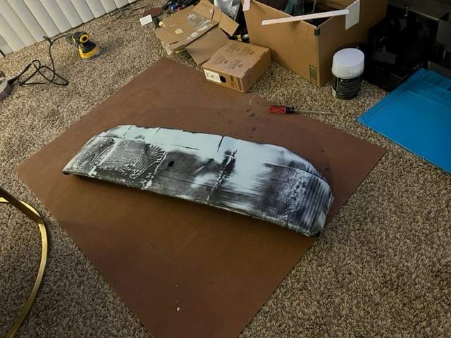
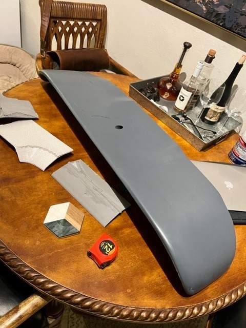
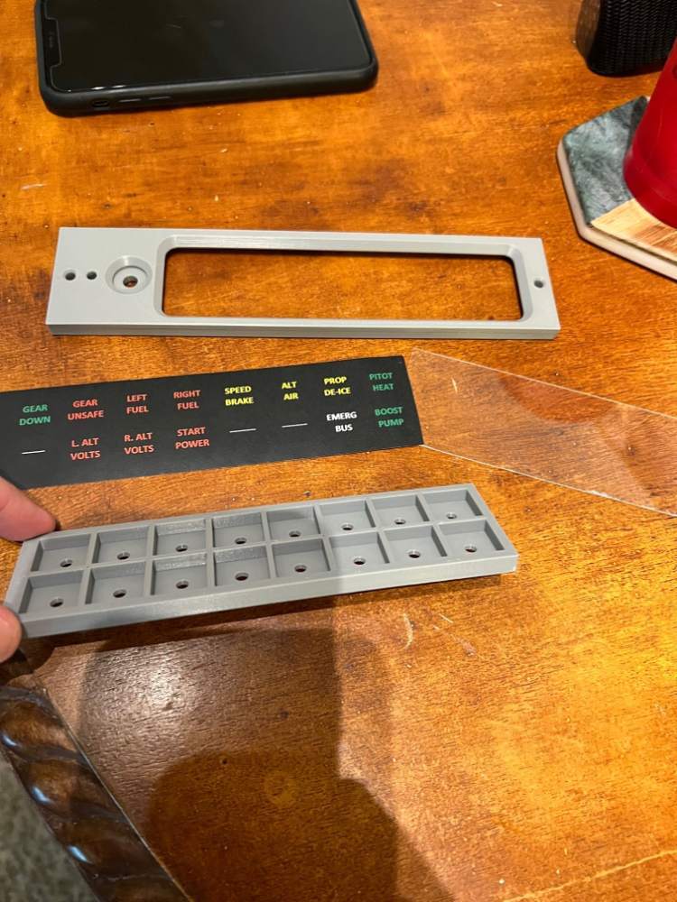
The dashpad is printed and I've applied bondo to help smooth it out, it just needs a little more sanding and it will be ready. I modeled a recessed area so that I can install a LED strip into the bottom of it to light the panel.
-
The panel has also been printed and just needs some bondo or CA glue to help hide the seams and it will be ready for paint.
-
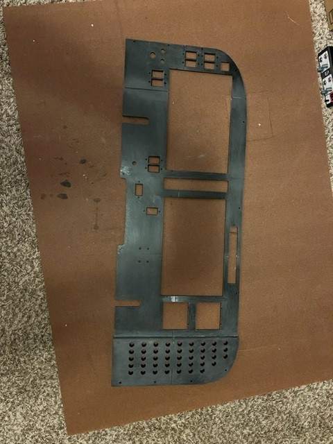
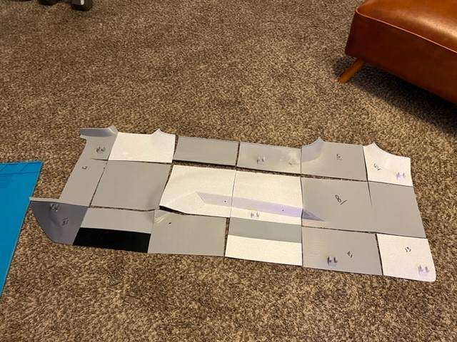
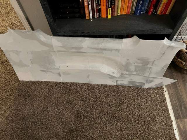
Progress on the left wall. I've printed it and touched it up with bondo to help remove the seams. It needs some more sanding and minor corrections and it will be ready for paint. The pictures can be deceiving, this piece is close to 5 feet long.

-
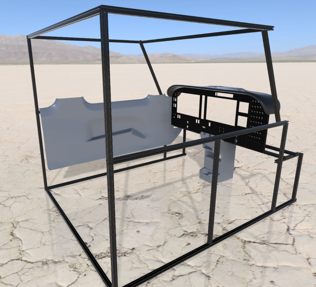
Update on the build since starting over on "Version 2". I've printed the panel, center vertical column that is below the panel, and the lower left side wall. Quite a time consuming project but I am hoping the end results will be well worth it. I had to figure out some type of bracket system to hold the walls and ceiling in place but I have a system now that is fully adjustable which will help tremendously once I start installing the finished pieces into the frame. Below is the latest rendering of the 3D model. All pieces shown are already printed.
-
Wanted to provide a quick update. I’m in the process of starting over on the new build. Currently printing the panel right now. I’ve swapped from using a 2x2 frame to using aluminum extrusion. This will allow me some flexibility on the brackets that will hold the interior in place. Pictures of the model attached are no where near finished but I feel I am making good progress.

-
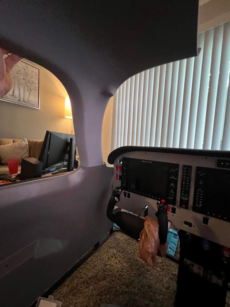
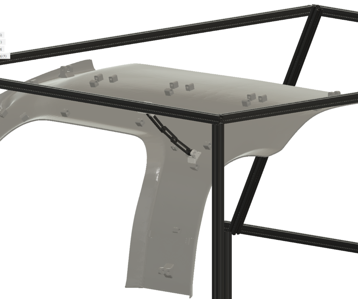
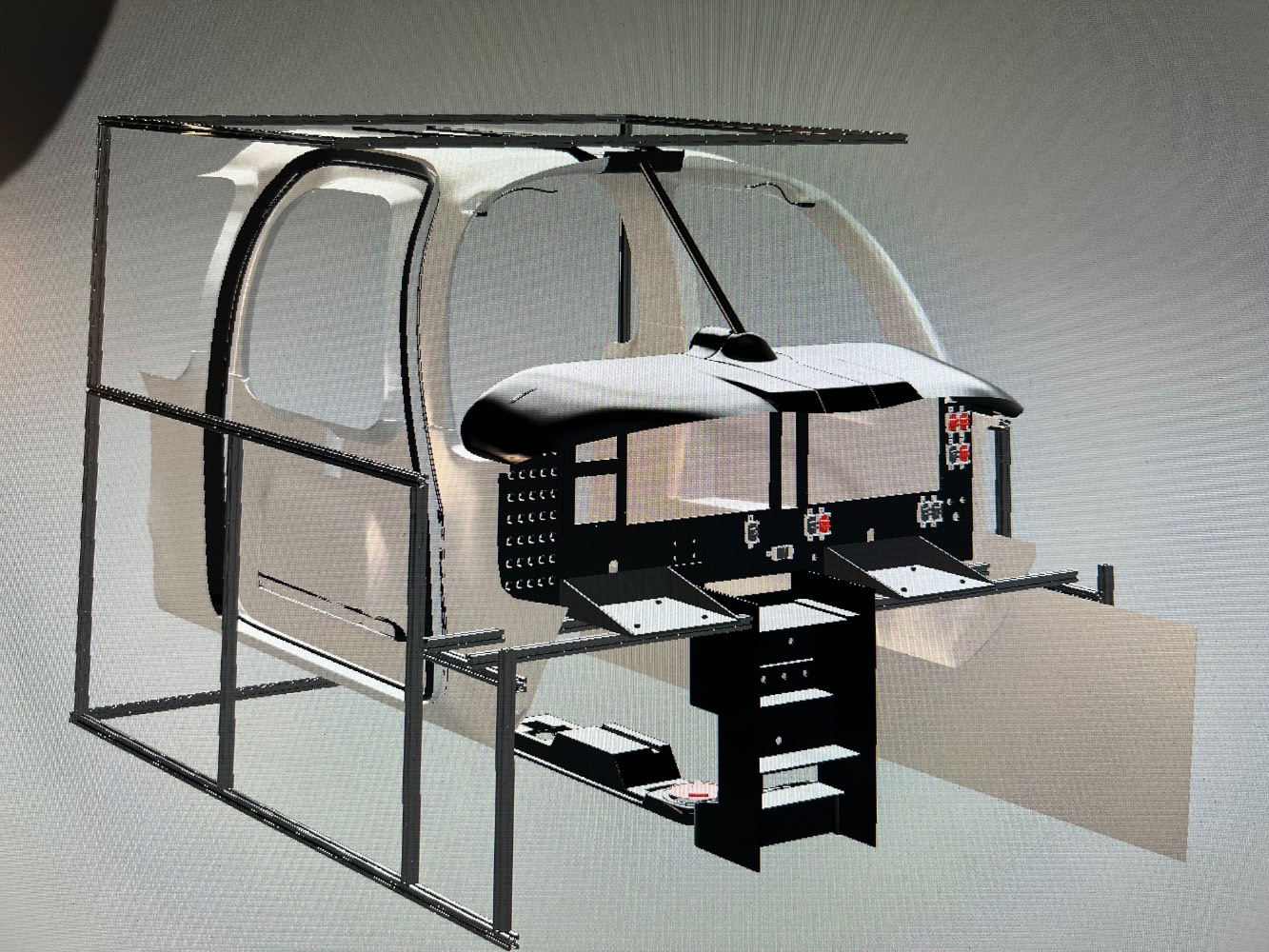
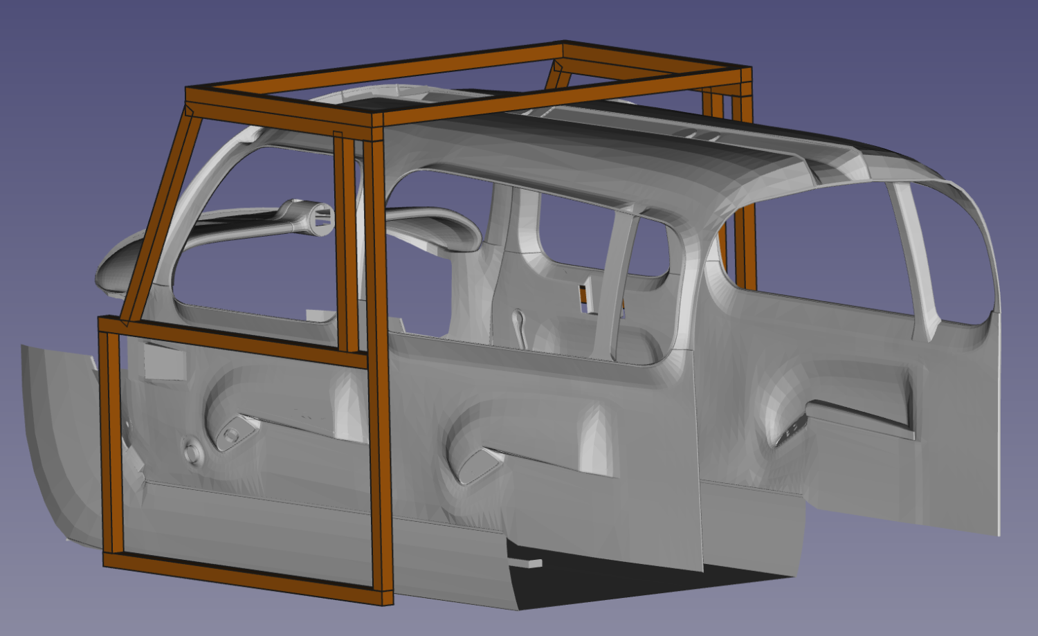
Okay... well this project just took a turn. After quite a bit of research, I have figured out how to export the object files from X-Plane into my 3D modeling program. For people with OCD, like myself, this is not good . I am now at a cross road because I now know that I can 3D print the entire cabin (granted after a lot of modeling adjustments to the M20 object file from X-Plane). I reached out to the model developer last night to make sure that I am not breaking anything in my license agreement if I go this route. All good there and he was very nice about it. Fortunately I have another Prusa 3D printer coming in today so now I will have three running 24-7 for the foreseeable future. Seeing that X-Plane 12 early access hasn't dropped yet, I may just go ahead and halt on the first version of the cockpit and move on to the 2nd version which will be a 1/1 replica of the Ovation interior (or as best as I can get with my modeling skills). I pasted in the model into my version 2 frame below to show a concept. Ignore everything behind the front seat area as I won't be modeling anything behind the front seats. This also gives me the ability to model out the yoke so I can replace the honeycomb yokes although I am not in a rush to do this as this is something that can be done later on.


-
-
Currently X-Plane 11 but most likely, by the time I finish all of the wiring, X-Plane 12 (Early Access) should be released.
-
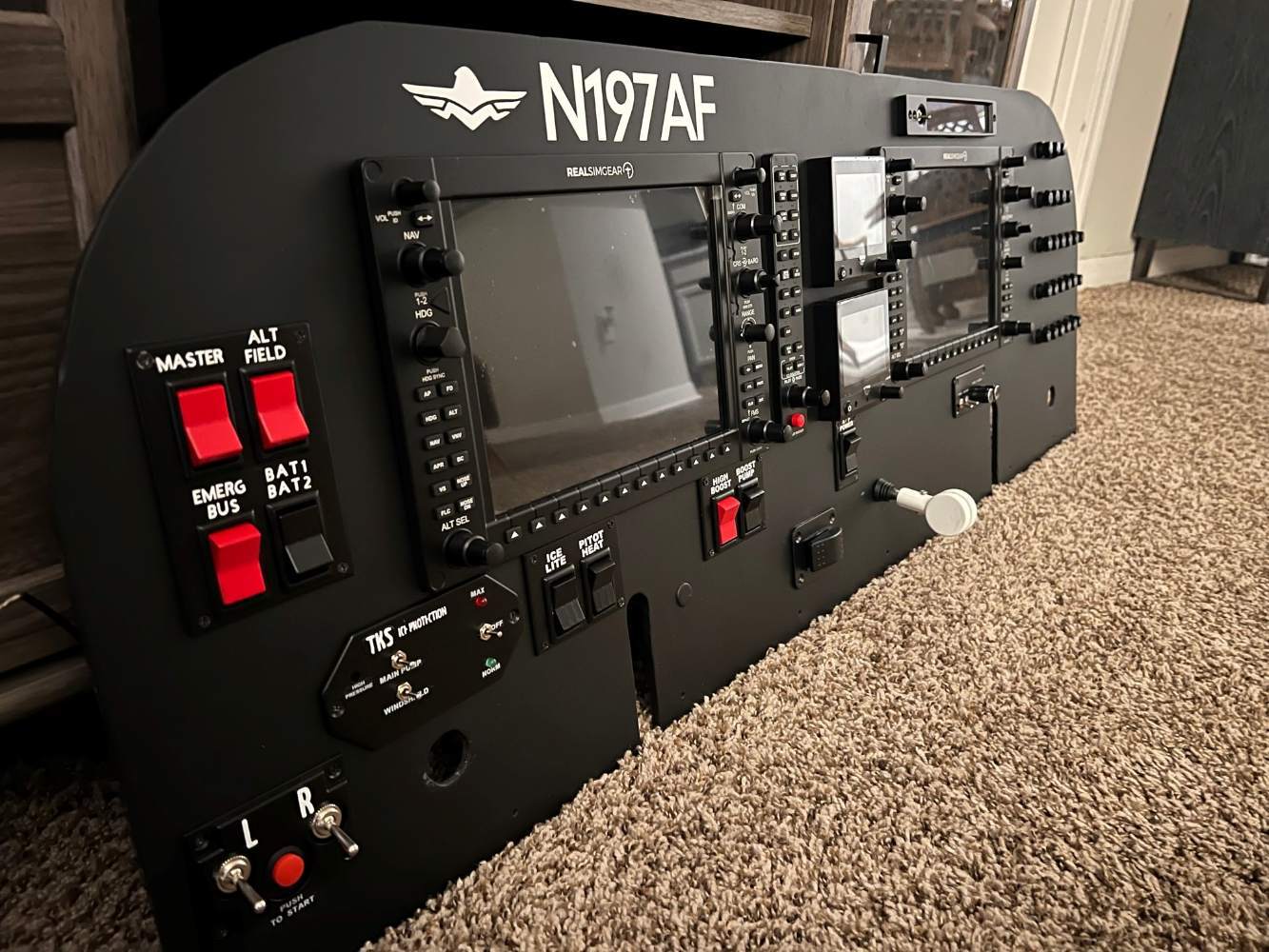
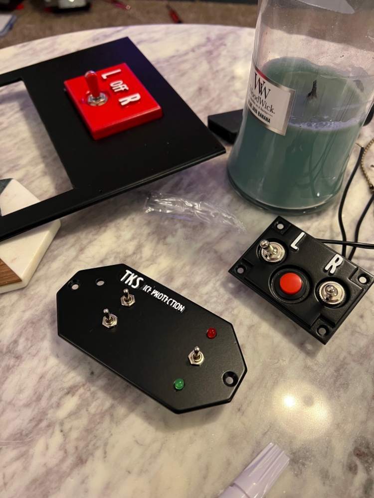
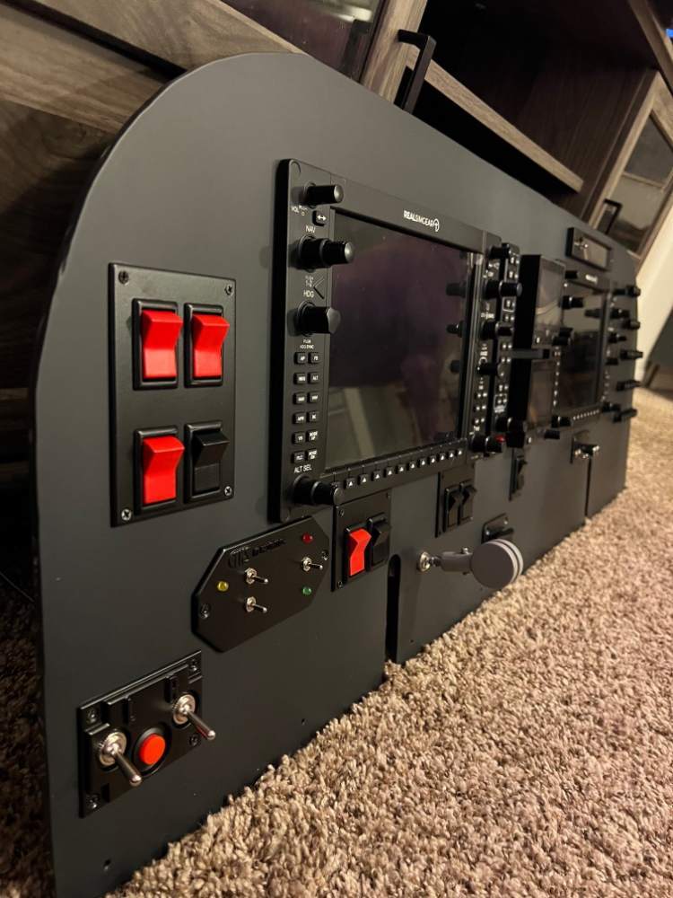
Panel Update: Although I don't love the placement and it will get changed for the 2nd version, I moved the gear switch over enough to clear the yoke housing behind the panel. Also added more vinyl decals but I still have a few to go. Hoping to get the decals finished so I can install the panel in the frame this weekend. I'm also not in love with the left/right mag and start button switch plate so I may redesign it before the panel is installed into the frame.
-
Thank you sir. I have two 3D printers, an Ender 3 V2 and a Prusa Mk3S. It’s been a journey for me learning how to 3D model. It’s been a journey learning how to model the parts and they’re very basic right now but I’m hoping to make more realistic parts for the 2nd version.
-
I’ll take you up on that! Messaging you now. Thank you
-
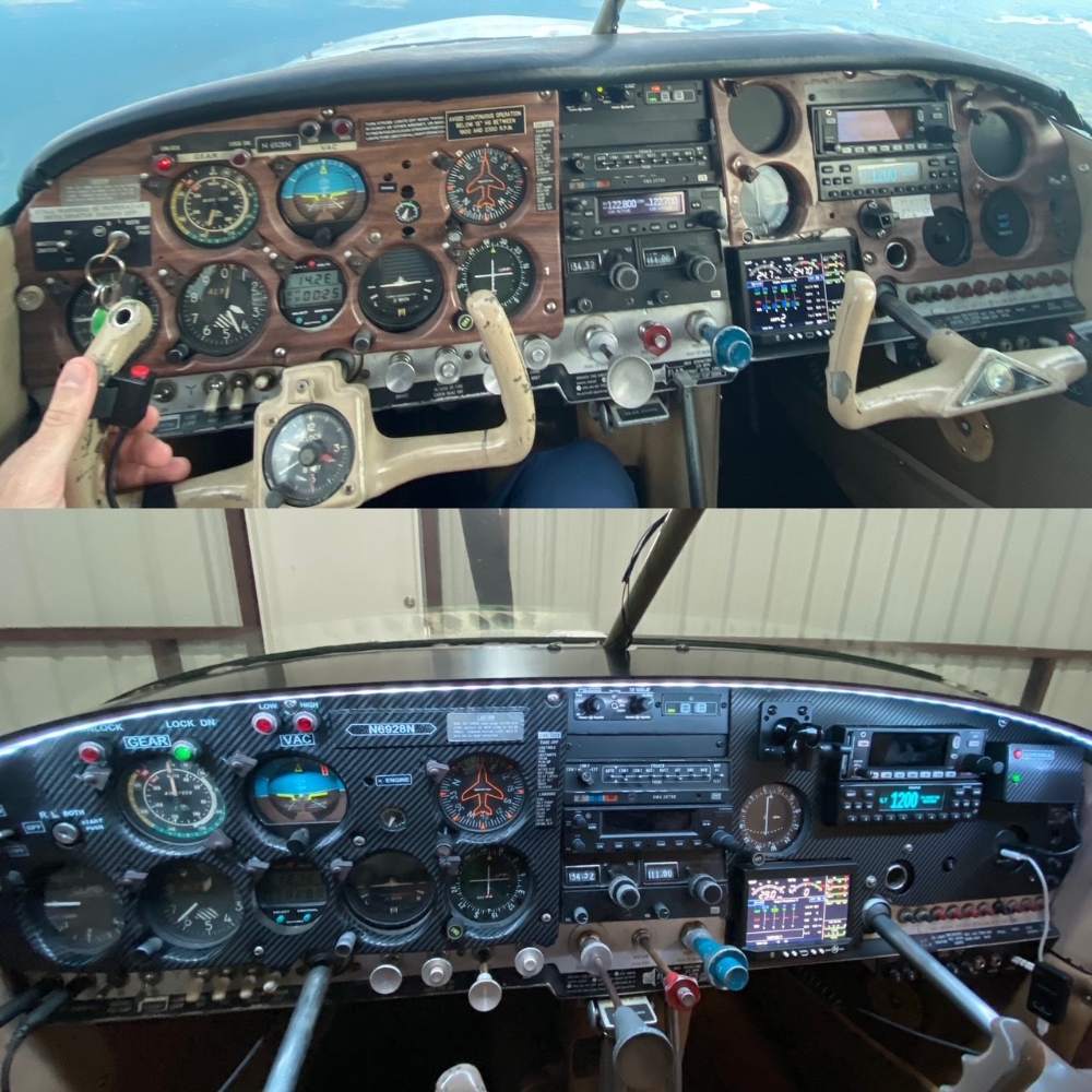
Hello all, I am working on building a M20R simulator. I am around 75% finished with the hardware setup and I already have plans for a 2nd version but that will take months of 3d modeling so for now the walls will be square. For monitors I am using Samsung QLEDs; 75" for the front and 32" for both side windows. I am trying my best to model the panel close to the actual however I don't know anyone with an Ovation/Acclaim to get better measurements so that will come when I decide to start the second version of the build. By the way, if anyone is around KBHM and wouldn't mind me flying to you or meeting somewhere I would love to get actual measurements and get some 3D images/lidar of the cockpit. If anyone has done something similar please share your setup and/or tips and tricks. I made a fatal error on the gear switch and placed it too close to the yoke so I am in the process of moving it. I will try and keep this thread updated for anyone interested in the build once it has been completed.


-
If you can send me specific dimensions, I can model and 3d print one for you. Although I don't have a way to etch, I wouldn't mind modeling and printing it.
-
X2 with Bob's comment. I made a glare shield for our '68C from lexan as I wanted it to extend a little further than the stock glare shield to install an LED light strip on. I also made a panel cover from lexan for the copilot side as the original copilot cover was hanging on it's last leg.

-
We're going to install an engine monitor in a month or two so we can better track any issues before they occur. Picking it up this Saturday from Air Mods. They are top notch people, Brian has been great for us to work with and has went above and beyond to fix items on it that we didn't even request him to correct. We're going to take the risk and check the oil and filter every 25 hours. Hopefully we will be able to burn most of build ups out and have a great engine for a few more years. If not, we will be prepared to over haul it.