
InJuRo
-
Posts
25 -
Joined
-
Last visited
Recent Profile Visitors
885 profile views


InJuRo's Achievements
")


-

Screws Inner Flap Mounting Bracket
InJuRo replied to InJuRo's topic in Vintage Mooneys (pre-J models)
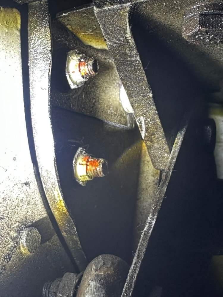
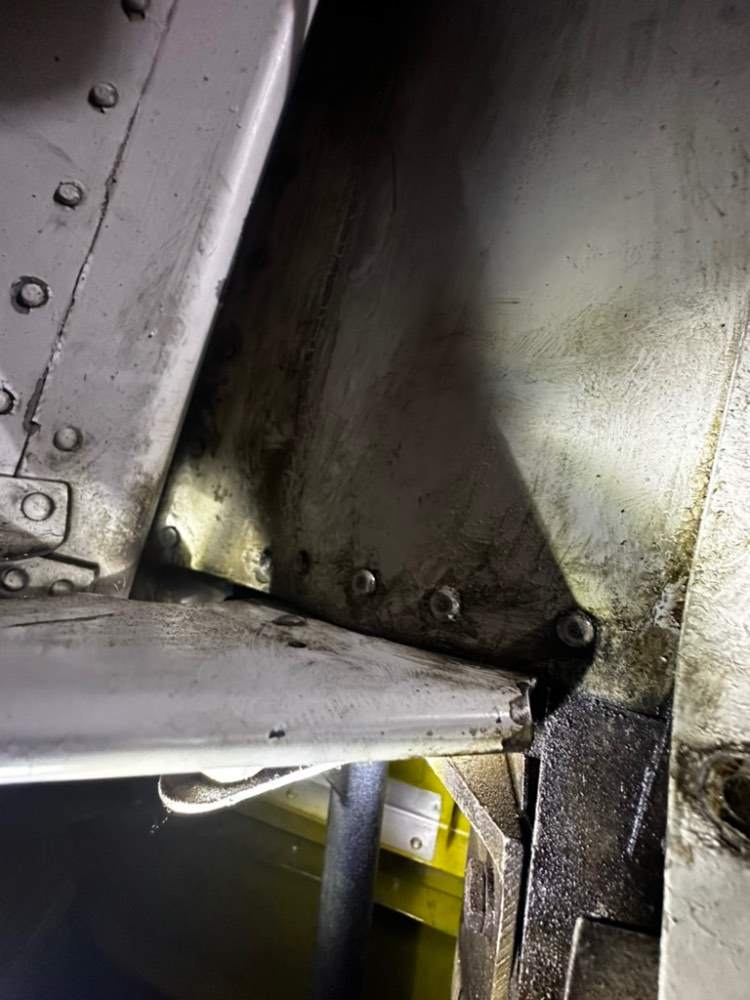
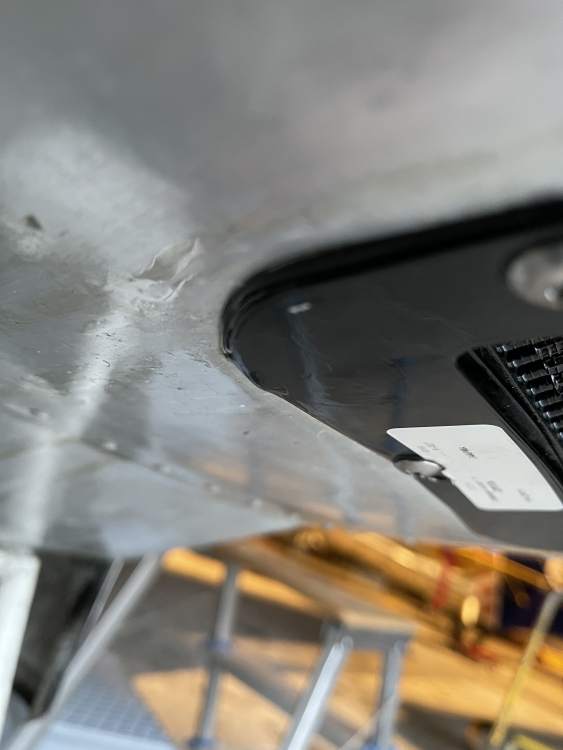
No, not really. 1. Did not see/feel any damage during preflight 2. While approaching, I deployed them and also checked visually through the window. Left one fine, right one "up". 3. While taxiing after landing (lower speed) it was "all down" 4. Back in the hangar I realized with a "wiggle test", that the inner mount is loose 5. Took of the lower belly cover and the small cover on the side and three screws, holding the flap mount (triangle) Shape to the spar, seems to be "loose" while still the paint marking on the nut is correct 6. I cannot access the head of the screw, so I have no clue actually, how to "tighten" them. Managed to tighten one and now flap is "good" again (wiggle test on the ground), but of course they all need to be tightened. Best regards and sorry for being a little unclear. Hard to describe. Ingo -
During my last flight with my M20E I realized during the visual check that my right landing flap did not "lower". The left one was fully deployed the right one was in some kind of nearly "full up" position. After Landing, while taxiing off the runway the flap was fully deployed. - Just to mention, flightwise it was no issue. I thought about putting the flaps back up but then (due to ice in the runway) took what I could get and it flew really well even with the flaps deployed differently. So far, so "good". After landing I checked the right flap and it turned out, that the inner flap mount, the "triangle shaped" bracked below the "step area" of the wing, was "loose". It could be moved a few centimeters/inches and as a result, the flap, even when deployed had so much "play", that the pressure pushed it back to the "nearly full up" position. I took the lower belly cover off and the little cover on the rear right side which is installed under this flap mount bracket. It seems like the bracket is mounted with three screws which are marked with red paint. These screws could be turned. They were not "loose" in a way, that the nut was loose (color markings were still good) but the did not really tighten the construction. I wonder if it may be a result of really low temperatures, age and the fact that alloy and steel expand and compress different. I would not like to tighten the screws/nuts. The problem is, that I can only access one side (the side with the nut) but not the backside. Did anybody ever habe this problem? I managed to "tighten" one nut with a mixture of a clamp and a wrench. And now the flaps has no play anymore. So this seems to be the issue. But of course I want to tighten (or if necessary exchange) all screws properly. Does anybody have an idea how to reach the "backside" of these screws? It does not work through the "handhole" which is close to it. This one only goes not to the complete back of the wing. Thank you for your help and tips Ingo

-
Is the engine off with the engine mounting frame or without? I have the Laser kit and it installs very close to the engine mount/frame. How close also may also depend on your oil cooler. If you have "welding spots", sticking out on the outer housing of the oil cooler, it gets even closer. If the housing of the oil cooler is flat, it is easier. I put some leather in between, to see if there is any contact during vibration. Installation takes "a motivated weekend". When the engine is installed, attaching the rear mounts of the baffles ist no joy. This may be much easier with the engine off. Nevertheless when the engine is off without the mount, be aware to retrim, when installing the engine. When you have the oil cooler installed, consider to close the gaps on the side with either e proper instant seal or bend yourself some aluminium which you mount in. The better airflow will drop oil temp by a few degrees. Otherwise with the relocation it felt like the oil gets a little bit hotter. Get a good and sharp drill to get rid of the rivets of the former oil cooler mounting frame at the front cowling. Ingo
-
Fuel Pressure needle reversed ‘64 M20E
InJuRo replied to Chocks's topic in Vintage Mooneys (pre-J models)
The Vent line goes to the belly of the front cowling and then ends "in the air", so that fuel simply "gets out". There is no connection to anything on the other side after it went through the firewall. Ingo- 25 replies
-
- 1
-

-
- fuel needle
- combo gauge
- (and 3 more)
-
Fuel Pressure needle reversed ‘64 M20E
InJuRo replied to Chocks's topic in Vintage Mooneys (pre-J models)
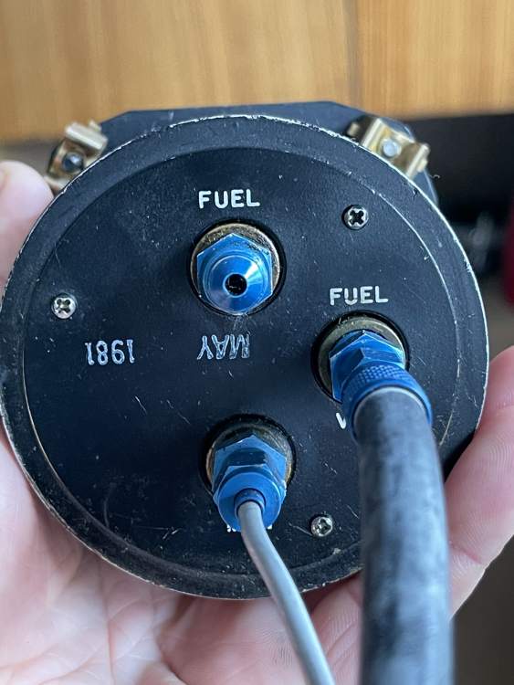
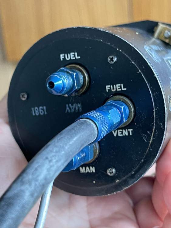
Increase in this case means that the indicator moves "down" or "up". I am not totally familiar with the mechanical construction of the instrument but if it moves "down" when you put the switch on, really check if it is simply connected the wrong way around, meaning vent and pressure port were mistaken. I add some pics of my old instrument. I also did a short test and blew (with the mouth) some air in the vent port connection. Et voilà! This caused exactly what you indicated, the needle reversed (went to the left). So I guess there is a high chance that one of the connections is wrong. There are ports on the back of the instrument, which are labeled MAN (Manifold), FUEL (Fuel in) and VENT (Fuel Vent port). They may be misconnected there or at the connection which goes through the firewall and will normally be slightly on the right half of the firewall (sie top of arrow). Ingo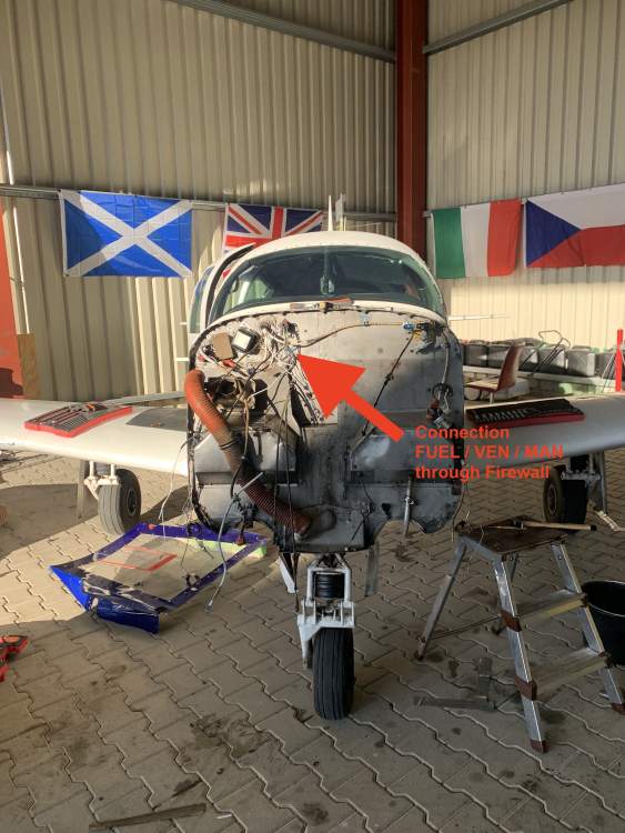
- 25 replies
-
- 2
-
-
- fuel needle
- combo gauge
- (and 3 more)
-
Electroair EA-15000 Ignition switch
InJuRo replied to NotarPilot's topic in Avionics/Panel Discussion
Propably not without modification. The Shower of Sparks has an extra Pin on the Bendig switch which is activated either when you "push" before turning to starter or with some other models just when you turn the starter. The Shower of Spark connector is marked with "BO" (Booster Output). You can find it in the installation manual for the Bendix TCM Switch 10-357210-1. This is a nice manual to the ignition switch. http://www.aeroelectric.com/articles/Shower-of-Sparks/ShowerOfSparks.pdf You can find the different connection "modes" on page 11. So I guess you'd need a switch which can ground the shower of spark at a certain mode. In the installation manual of the Ignition Panel, the shower of spark system is not mentioned and it seems like there is also not connector for it. http://www.electroair.net/pdfs/EA13000IM.pdf Ingo -
Tomorrow my new seats will come. When they are back in, I want to do an oil change anyway and I will "taste" the oil The cowling is dessert dry inside. Oil filter was not oiled when the engine was changed. But we will see, when it was running. Thanks for all your help.
-
Fuel Pressure needle reversed ‘64 M20E
InJuRo replied to Chocks's topic in Vintage Mooneys (pre-J models)
If I remember correctly there are two fuel lines on the back of the instrument. One to the instrument and one "vent line" back through the firewall which should end somewhere on the belly in front of the gear. In case the inner membrane of the instrument brakes and the fuel "passes through" it is then cleared through the vent line. When the EMS was hooked up, did you you use the same fuel pressure port for both instruments? -
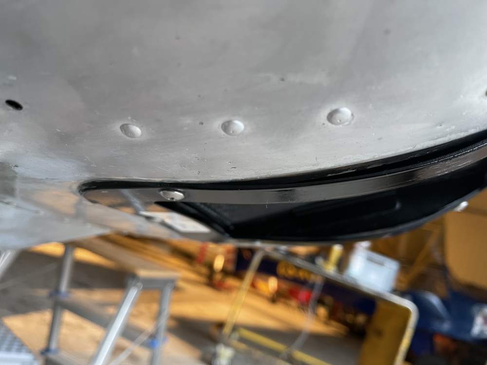
As it is not yet running (interior is redone) I can only send the pic of the air filter bracket so far. On the side view (left picture) you can see the "non-optimal" fit (was the same with two different cowlings). On the other picture (right one) you can see where the oil "runs" after shutdown (shiny spot left) which is the side of the filter facing the front gear. Will take some more pics as soon as practical. Ingo
-
Fuel Pressure needle reversed ‘64 M20E
InJuRo replied to Chocks's topic in Vintage Mooneys (pre-J models)
One more thing.... Does it change when you turn the electrical pump on? -
Fuel Pressure needle reversed ‘64 M20E
InJuRo replied to Chocks's topic in Vintage Mooneys (pre-J models)
Did you change any other connections? Both instrument are connected through the firewall and with the older Mooneys the fuel pressure may be taken from the distribution spider on top of the cylinder. There the pressure at the spider distribution port is lower than at the fuel pressure port, so if connectors or tubing were changed, there may be a wring pressure for the instrument and it goes on "max"? I had this issue when I got an EDM. When you connected it to the former pressure line of the instrument, the reading was minimal as pressure was taken from the distribution spider. Do you have a EDM installed? Ingo -
@carusoam Thanks for the input. EDM-Data is all good (EDM 900). Mag-Tests are smooth. No white smoke, neither with start, nor at any other time. Turbo is dry like a dessert. It definitely comes "from the top", so from the Rajay Airbox. I like this challenge also (even as it tends to be a little bit annoying) @N201MKTurbo Santa Barbara sounds like a good option. Cold and Rainy here in Nuernberg, Germany. The air filter has the inner bracket with the filtering mesh and an outer "mount" which with the Challenger consist of a rubber seal and a flat metal frame which is screwed on the cowling with six screws. The production quality of this mount is moderate at least and the shape does not fit perfectly to the cowling. There is no risk of dirt or dust getting in as the inner filter bracket fits "tight" to the side of the cowl but the rubber seal does not prevent any oil from passing by. I will try to take a pice. Just may take about 1 1/2 weeks as I am getting the seats redone.
-
My Mooney M20E actually has an Astronautics Pathfinder Autopilot but will go for a Garmin GFC500 soon. As I already have the side panel out, I want to route the wires to the servos already, so that they are prepared and I do not have to take it out another time then. Can anybody tell me where in the wing the aileron servo is installed? Will it be at the same place where actually the Astronautics Pathfinder Servo is placed? I found how the ones in the rear are installed so it is no issue to prepare these cables already. But I wonder about the place in the wing. And concerning the Canbus-Cable do you know if it was terminated in the wing, so the wing servo is the final one or wether it is common to route from the panel to the aileron servo and then continue to the servos in the rear? Ingo
-
InJuRo changed their profile photo
-
Connector Identification Help
InJuRo replied to flyingchump's topic in Vintage Mooneys (pre-J models)
I think my connector of the ADF Antenne in my M20E looked like this. Do you have a fitting "hole" (which may have been covered) in the belly underneath? @N201MKTurbo was faster I guess Ingo -
I will check for the issue Jim described. But as is is the same filter as before, I can hardly imagine why it should drip now besides maybe that the temperatures due to the normalizer installation got higher and therefore the oil now partly drips. On the other side, I had taken the oil filter away and the oil was in the upper air chamber of the Rajay (directly oder the oil filter). As the oil may not "jump up", it has to come from the top. The engine has absolutely no "white smoke". It runs clean. Absolutely no oil on the belly and no oil at the tail pipe. So far I do not find any oil missing. The engine uses little oil. I found in the Bonanza-Forum that this seems to be common with some engine and may be gone over a while or maybe not. There are some who write that even after 600 hours, there is still some oil dripping and some that say after 20-30 hours it is gone. They explanation was that this is conservation oil. On the other side it was also written, that these may be leaking valve guide seals. But shouldn't there be white smoke then? I guess next is to take off the lower cowling and take a good look into the intake system. Ingo


