jM20
-
Posts
21 -
Joined
-
Last visited
jM20's Achievements
")


-
Thanks all for the feedback!! I'm finally getting back to the issue since its in annual now.. I took the sender out and hooked only the center wire up, and then grounded the casing. The gauge reads 1/2 full when empty. When I lift the float to full, the gauge reads way past full. The gauge does go up and down with movement of the float up and down. The zero is just off! I tried to bend the stop a little, but it only seems to make things worse. Onto repair, next step try to see what the resistance is? Thank You!!!
-
That was a mistake! Forgot to tighten the screws down again after screwing around with the probe and then went flying. It’s not straight forward what orientation the probe should be in either…
-
I’m not sure, I don’t think so. What im really not sure about it where the ground contact point is on the sender.
-
I’m just not sure where the ground should make contact? It doesn’t seem to from the screw holes themselves.
-
Hi! I'm not sure if im missing remembering or not. We took the float out to do a tank repair. After putting the float back in, the reading on the gauge was past the top. There is only one wire going to the sender. I thought the problem was a bad ground, so I attached a wire to the post and the other end to a screw. I managed to short the gauge now so that it only reads 0. I looked in the manual and its of no help how this goes back together. I'm pretty sure I looked at the other side and it looks like I put it together correctly. Any ideas? Thanks in advance!!

-
Thank You!!!
-
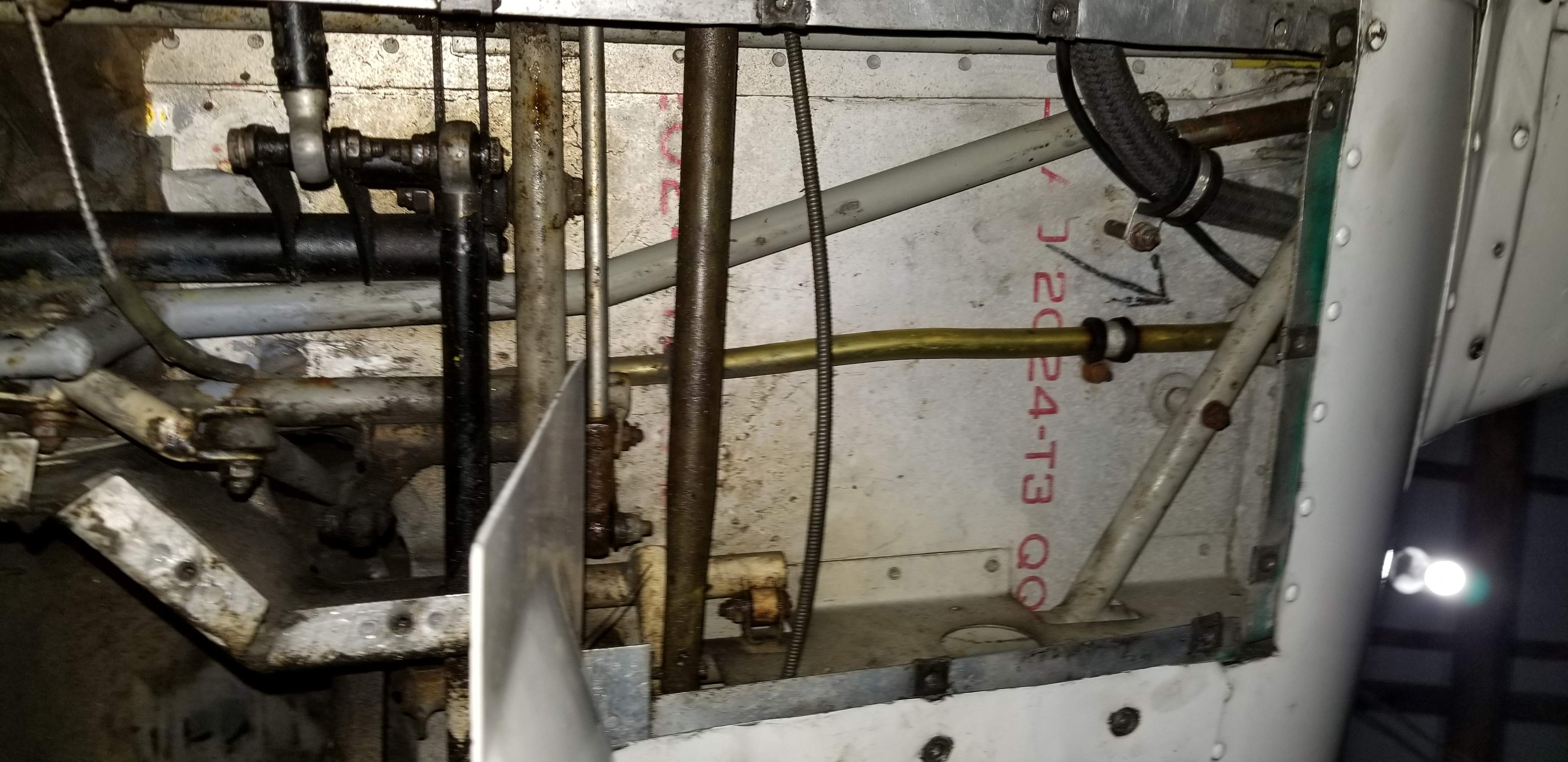
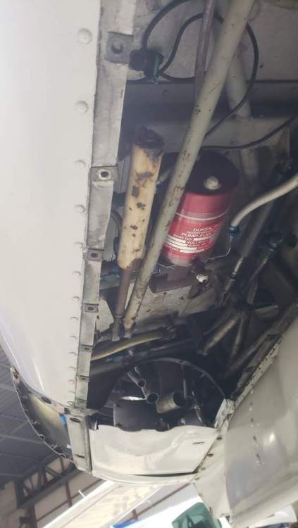
The white looking shock absorber is attached to the nose wheel linkage. The image is the port panel area next to the nose wheel compartment. Any idea what it is? Part number? I can't find anything about it in the service manual..
-
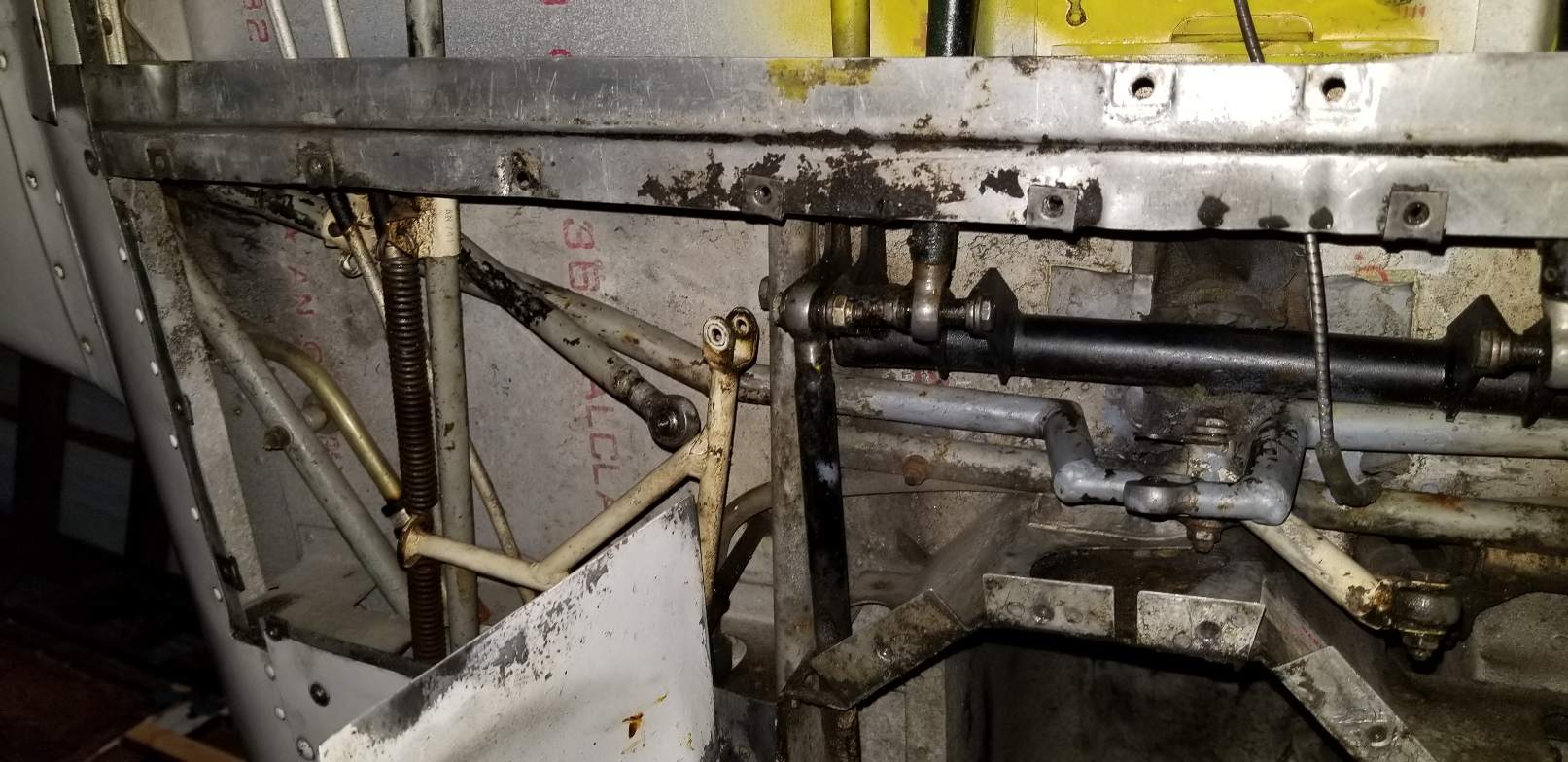
Thank you everybody for your responses. James the item that is directly in the way is the landing gear framework. I thought that it might have to come out, but it completely makes sense that if I stroke the gear it would move it far enough out of the way.
-
The links are completly free, just cant figure out how to rotate them out. Had two people try. I guess the big question is, what else has to come out? But it sounds like nothing.

-
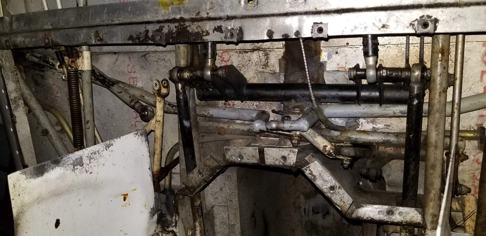
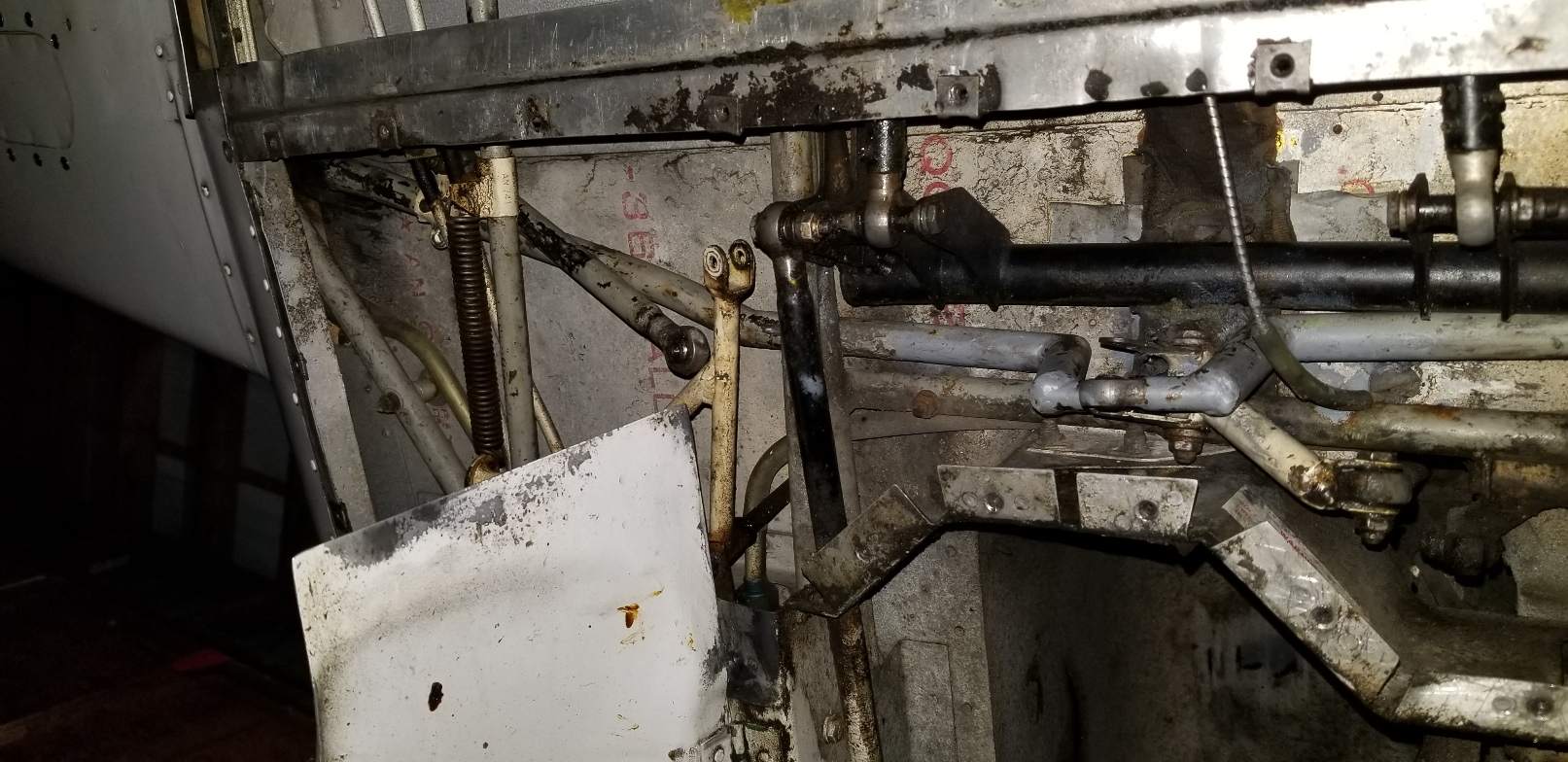
Hi, I have an issue with removing center control links for AD M20-264-002. I have them completly detached but can't get them out to get them serviced for the AD. I attached pictures of my dilemma, how do you get them out? The links are the grey with the 90 degree arms which are stuck under all the other bars. Thanks!


-
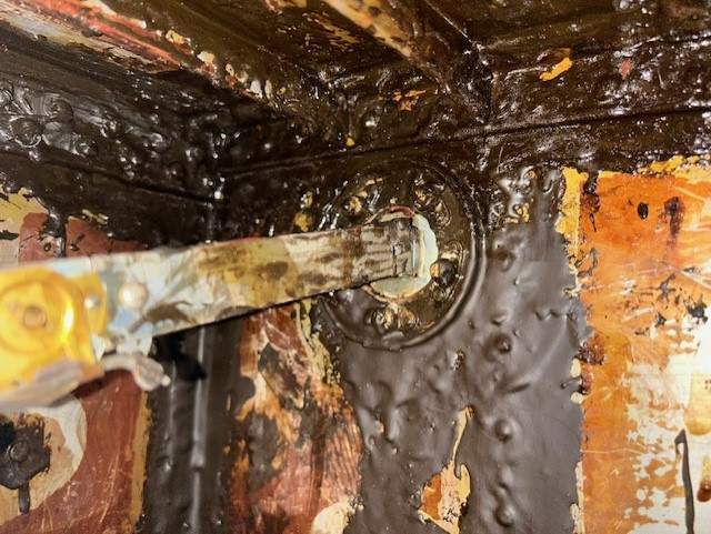
Follow up. Well I finally got everything put back together. It turns out that the black mark you can kind of see is the Low Vac. The yellow is High Vac. The non colored is the Power. I was a little surprised the yellow was wrong...
-
Thanks for the clear photos!
-
According to the schematic if you can see the pdf, the black is on the wrong one.....
-
Help again! Well I was installing a new heading indicator and accidentally knocked the wires off the back of the vacuum switch connect to the heading indicator. I have a big contradiction. The yellow mark is for low vacuum. There seems to be a black mark next to another screw port. However, the appearance of the black mark contradicts the drawing from Sigma-Tek attached. Anybody have this on their 60's M20C and can check? Thanks in advance! Regards, J 22-1280-04.pdf


-
Does anybody know pretty accurately, what the full stroke of your throttle handle is? Thanks!