

L. Trotter
-
Posts
164 -
Joined
-
Last visited


L. Trotter's Achievements
")


-
Brian Kendrick has been maintaining my Acclaim for several years. You won't find a better mechanic who understands Mooney's in the industry. He was the lead factory mechanic for years. He's a busy guy, if you can get him to maintain your plane it's a real treat. It's worth the trip to San Marcos.
-
You want the Scott connector. I had two separate problems in my Acclaim oxygen delivery. 1- I visited Precise Flight in Oregon. I took perhaps 20 green Scott connectors and found several that worked without a leak. I'm not not sure why some of the connectors leaked. The folks at Precise Flight felt it was a combination of manufacturing variances between both the connector and valve outlet-one a little small, the other a little big. I was about to replace the valve in the plane (not a small task) until I tried different Scott connectors. Of note, after talking with far too many people about this leak issue, I could find no one who had experienced complete failure of a valve requiring replacement. Not that it cant happen...it's just extremely rare. 2- I used hospital O2 tubing as part of the nasal cannula. Most hospital O2 tubing has raised internal "ribs" inside the tubing (I suppose to keep it from kinking). This internal raised area allows O2 to leak around any connection points. specifically at the Scott connector.
-
Now you are starting to sound like a back country bush/STOL pilot. Back side of the power curve.....
-
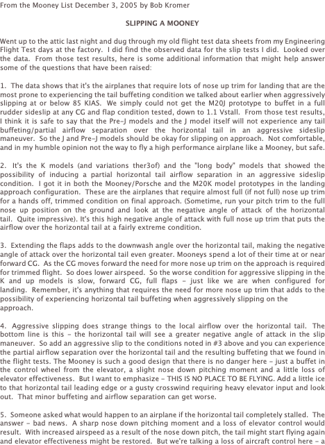
Late to this party. Here is an article by Bob Kromer in regards to Slipping a Mooney. Also, if you have relatively full fuel tanks, you will see precious petro exit the low wing tank through the vent. SLIPPING A MOONEY.docx
-
I am based in Rapid City (KRAP). Although it may not help, perhaps I can shed a little light. Ellsworth is a training place for controllers. Generally speaking, they are well supervised. However, you can get some young controllers who are still learning their trade. It is not unusual to receive some interesting instructions. On occasion, I have called them on a land line in efforts to help them help us more efficiently. They are happy to provide you a phone number should you ask. Additionally, some of the controllers in the Rapid City tower have worked at Ellsworth and are well acquainted with their system and can help as well. As far as the instructions "hold as published" while flying a direct airport to Airport flight plan, begs further clarification. There are 5 separate published holding patterns in the Rapid City area ( HELTA, EWEBU, COTTY, MUDDY and RAP). I can almost guarantee you they were referring to RAP because this is where they typically take us (as a routine) for practice holding and missed approaches. The HELTA fix, associated with the published ILS approach is a relatively new fix. Additionally, the seasoned controllers would have given you a visual approach in VMC if they had radar coverage. Unfortunately, the local radar coverage has been inconsistent while the system is being overhaul. Hence, they're need for a holding until previous IFR traffic has landed. This experience would have been a great teaching point for a young controller. In my opinion, you should have been provided a new clearance direct to a holding fix of their choice with appropriate holding instructions to include expected time of release.
-
Had a long discussion on this very topic with the TKS folks before installing the system on my Acclaim. They are quite certain the TKS fluid and system DO NOT cause corrosion. I guess I would expect nothing else from their perspective. However, the corrosion issue seems to be discussed primarily with in the Bonanza community. The area of corrosion is typically in the same place....the spar right behind the TKS panel. There is a "spar" seam unique to the Bonanza wing that Mooney's don't have . Not certain if it is a metal mis-match interface or trapped moisture with in the seam (favor) caused by the TKS fluid indirectly. I am unaware of Mooney's having this same issue or hinge point issues.
-

What I have learned about LED landing lights
L. Trotter replied to PTK's topic in General Mooney Talk
What I learned about LED lights......... I had an interesting experience with my new Aero-Lites LED PAR 36 landing/taxi lights.They're mounted in the wing of my Acclaim. This past week I was traveling from Provo, Utah to Wausau, Wisconsin. I encountered icing in route and made good use of my TKS system (what a nice addition). For those not familiar with TKS, the entire wing leading edge is protected except the lenses of the landing lights. In the past, with my incandescent GE bulbs, I could turn the lights on and the heat produced would melt the ice on the lenses. The outside temperature just changed the length of time required, maybe 15-30 min if real cold (> -10C). With the LED lights on for >1hr @ -5C the 1/8" layer of ice did not even budge. Granted this is far from scientific, but a real world observation...A good thing or not, you decide. As for me, the pros of less heat out-weight the cons. By the way, I love these lights. Even after > 1hr use, they are extremely bright and far better at illuminating the run way/taxi ways than the original GE bulbs. -
SOLD *******. Long Body Landing Light Lenses
L. Trotter replied to co2bruce's topic in Avionics / Parts Classifieds
I've got the answer for you… Just recently completed this project myself. Expect about 1-1.5 hrs to complete. Use your old lens and a black sharpie to mark a rough outline on the new lens. Put the old lens inside the new lens. Make sure you're a strong 1/4 inch too big. Then, use a belt sander flipped upside down to gradually sand away the excess lens material. The belt sander should be a relatively fine grit. Keep checking fit after removing small amounts of lens material. I repeatedly used the sharpie to mark material I needed removed. Just go back and forth between the fit on your plane and the sander. You do not want the lenses to fit perfectly tight. You need a small gap all the way around to allow for expansion and contraction or the lens may crack at one of the screw sites. Now comes the fun part.....Drilling the holes. I would suggest obtaining a drill bit specifically for plexiglass. You can use a generic drill bit but they are very aggressive and you may find that they crack the plexiglass material. I used the old lenses and drilled multiple holes just practicing before moving on to the new lens. Place the new lens in its position on the wing (after fitting is complete) and with the sharpie mark each of the screw holes sites. MAKE SURE THE LENS IS HELD SECURELY IN PLACE WHILE MARKING. Then, with the lens secured on a firm surface (I used wood), Drill each of the holes without hesitation. Don't be timid at this point or you'll mess up. I had 2 drill sizes, one that perfectly fit the screw, the other slightly bigger to accommodate the shaped washer. If the smaller hole was not in perfect position (on trial placement) you can cheat a little from one side to the other with the larger drill bit thus allowing the hole to line up properly. -
RPM's on G1000 showing "0", during Engine Operation
L. Trotter replied to Mooney_Allegro's topic in Modern Mooney Discussion
I had the same thing....There are 2 round wire harnesses on the pilot side adjacent to the fire wall. They are easily accessed by removing just the top cowling. Disconnect and clean out both sides of the harness with an electronic cleaner. This will be a good first start. If no improvement trace wires to find break. -
How to replace landing lights (to LED)
L. Trotter replied to L. Trotter's topic in Modern Mooney Discussion
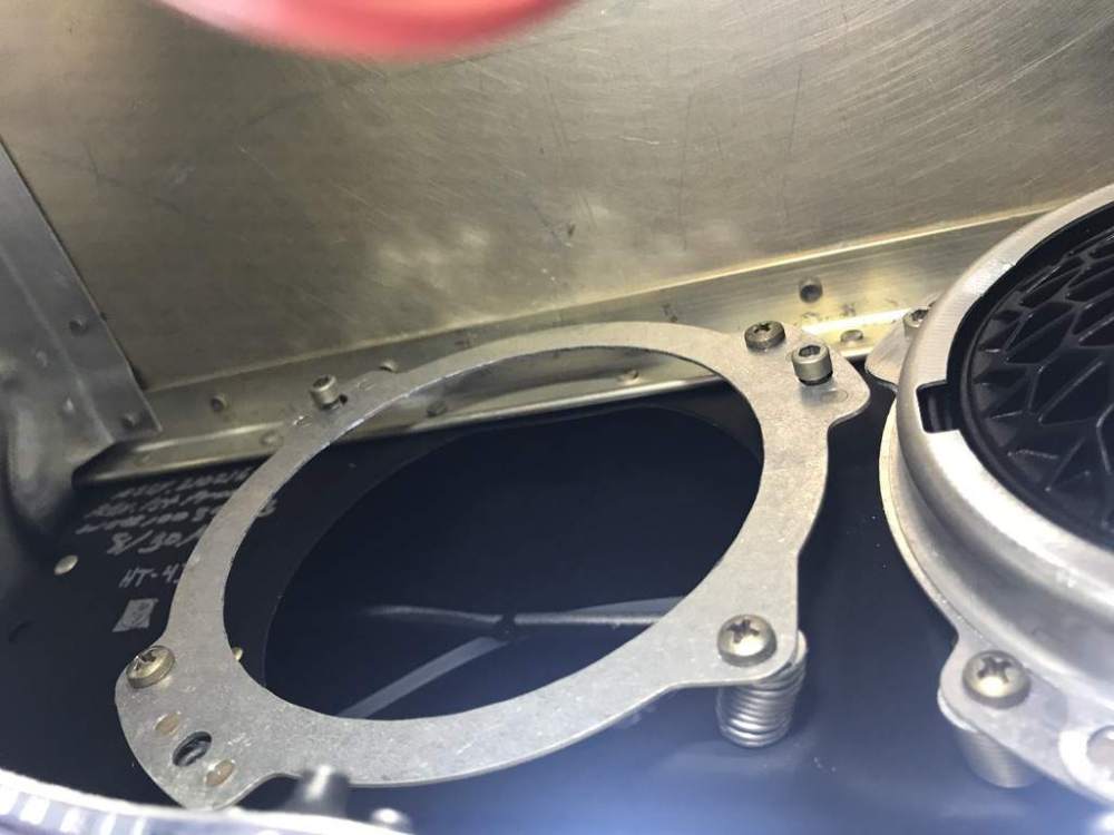
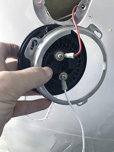
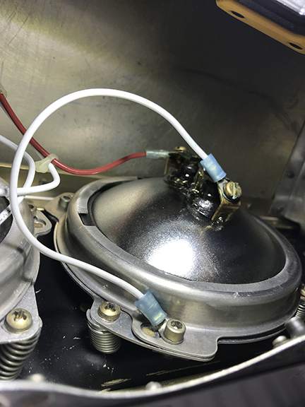
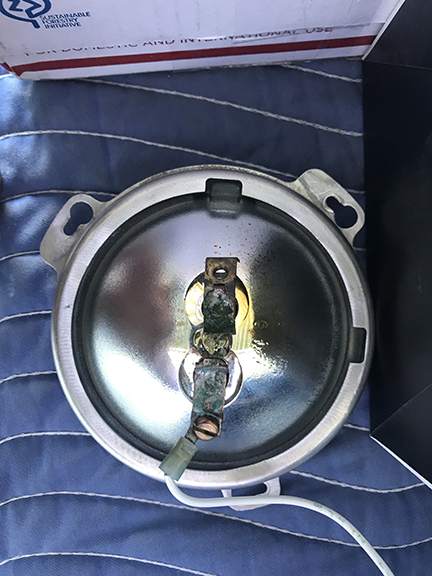
Yes, they are factory. There is an aluminum bracket that fits on the back of the bulb that in return is attached to a more permanently mounted base. You can see this set up on the 4th picture down. On the left is the base with no bracket or bulb. On the right is the bulb with bracket holding bulb in place. The 5th picture down is the bracket coming off the bulb. -
How to replace landing lights (to LED)
L. Trotter replied to L. Trotter's topic in Modern Mooney Discussion
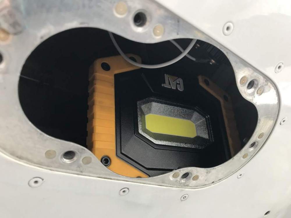
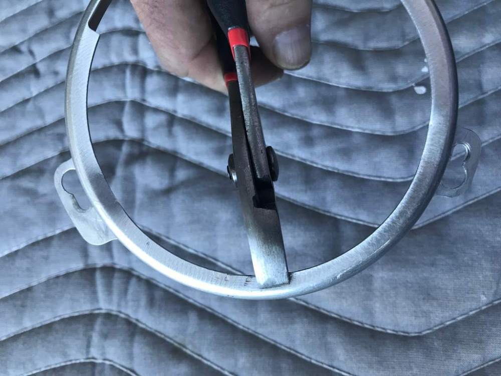
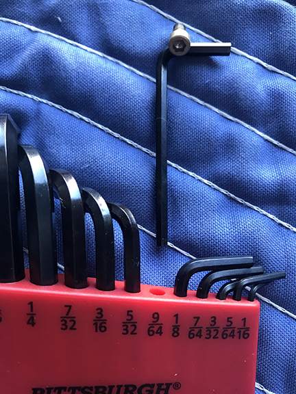
Job completed...Here is how I replaced the landing/taxi lights within the wings of my Acclaim (replaced the GE bulb with LED-PAR36). I am NOT an A&P and make no claims that this is the best way. It worked for me. For starters -Really Mooney!, could you not have put a larger access panel (like the dozen other larger panels) at a location you actually work through. -If you are inclined to swear, you may want to learn how in a few different languages. There are not enough profane words in the english vocabulary to complete this job. -Plan to spend about 30-45 min on each light. Go slow or risk cut hands. -I would never consider replacing the old GE bulb with another incandescent GE bulb. LED all the way!!! If the only benefit of LED was to never replace again, it's worth it. Equipment needed: 9/64 allen wrench, shorty slotted/phillips screw drivers, small light, pliers, ?tape Steps: 1. Make sure the light and master switches are in the OFF position. Remove (small) panel immediately behind landing/taxi light. Landing lights are inboard/taxi outboard. It is not necessary to remove the clear plexiglass curved lens. However, it's a good time to consider cleaning them up a bit. I used a kit from "Mothers" called NuLens. It really cleaned up the lenses well-they look new. 2. I found that a small light, place through the access panel was very helpful and allowed much better visualization. 3. Take plenty of photos (before removing anything) to refer back on as needed. 4. There is such little space to work, removing the wires from the back of the bulb first (and pushing them out of the way) is helpful when trying to access the allen screws . The wires will be attached to the bulb with a slotted or phillips screw. Maybe even one of each like mine-go figure. The GE bulbs may not be marked + and -, so just remember the ground is the short wire attached to the bulb frame. If you forget, don't worry it will be easy to figure out latter. 5. Now this is important....Do not move the phillips head screws that are adjacent to the allen screws. These phillips screws adjust the light position and have nothing to do with changing the bulb. Perhaps you may need to adjust the light position later but that is a separate procedure/protocol. 6. Now the fun starts. There are 3 allen screws ( size 9/64) that need to be located (about 120º apart). 2 will be visible, 1 you will not see (you can only feel it-at the 2:00 position outboard, 10:00 position inboard). The allen screw located on the bottom of the bulb bracket will have the ground wire attached to it as well. Remove this screw completely and set it (with the ground wire aside). The other 2 allen screws only need to be loosened - not removed. 7. Once loosened, the bulb aluminum bracket will rotate slightly (counterclockwise) and then pull off the back of the bulb and off the light housing. 8. Now that the bulb and aluminum bracket has been removed you will notice an indexing tab on the back of the new bulb. There is a corresponding notch on the aluminum bracket that will ultimately be placed at the 12:00 position when installed. The bracket actually has 2 notches. This is a universal part that works on both inboard and outboard positions. The spacing of the allen screws are not exactly even. It is a good idea to insert the empty bracket to figure out which is the proper 12:00 position notch. 9. With a pair of pliers bend the inner lip of the aluminum bracket down towards the screw tabs. This will hold the bracket tight against the bulb. If you don't have enough bend to this inner lip the bulb will be sloppy and move around despite the bracket being fully tightened down. I put a good 20-30º circumferential bend in it. 10. To reinstall, line up the bulb indexing tab to the proper bracket notch and place at the 12:00 position on the light housing within the wing. I found that backing out the 2 remaining allen screws (almost out-but not quite) allowed things to line up easier. Twist the bracket clockwise making sure the tabs are properly seated with the allen screws. Now tighten down the one visible allen screw (for now). This maneuver might be easier if you place some tape on the new bulb to hold the aluminum bracket in place prior to tightening the first allen screw. Make sure to remove the tape if used. I did not use tape and had no problem. 11. Next, replace the ground wire with its associated allen screw to the bottom bracket tab and the other end to the back of the bulb. 12. Connect the positive wire to the back of the new bulb. Before tightening any more allen screws test the bulb to see if it works. If you have the proper wire polarity to the bulb put on your sun glasses because the LED light is bright!! If you have no light just reverse the wires on the back of the bulb, and re-test-no harm done. Despite replacing the wires identical to their original position, two of my lights needed reversing of the wires. Make sure the light and master switches are OFF after the function test is completed. 13. Now that the light test is successful, continue to tighten all allen screws securely. Make sure the notch is lined up properly to the indexing tab before you put all the effort in to tightening. 14. Repeat steps for the other 3 bulbs....ouch. 15. Wipe down the lenses from the outside to remove hand oils/fingerprints. Replace newly polished outer lenses. 16. Before replacing access panel, move all the wires so they are not touching the light bulb or housing....these get hot.

-
Getting ready to replace the std GE bulb with 100% compatible PAR 36 LED landing lights (two lights in each wing). It seems this is a relatively straight forward procedure accomplished through the access panel behind the lights. Any tips/advice before I get started?
-
Recommendation for LED landing light
L. Trotter replied to NicoN's topic in Modern Mooney Discussion
My personal opinion as well. However, I have a purist A&P/IA who wants paper on everything (not suggesting this is a bad thing). I think I'm going to just place and ask for forgiveness latter. I can check for radio interference on my own (a very low risk from what I've read). -
Recommendation for LED landing light
L. Trotter replied to NicoN's topic in Modern Mooney Discussion
Those of you who are using Aero-Lites (Sunsetter), are you getting a field approval (337) or going with the idea that these bulbs are an equal replacement for the incandescence bulb? -
So, I was at FL 210 temp -27C when I experienced a primary alternator failure ( alt new 150 hrs ago). The back up alt worked fine. I had very little load on the alternator when it failed. No circuit breakers popped. I landed for fuel for about 1/2 hr, temp +5C. I was expecting the primary alt to remain non functional. However, after things presumably warmed up a bit, the primary alt started working just fine. No further issue past 75hrs in temps as low as -15C. I believe the cold combined with very little load caused some sort of alt disfunction. Could cold temps be an alt limitation? Or do you turn every thing on creating a heavy load when temps are low?


