

cnoe
-
Posts
1,449 -
Joined
-
Last visited
-
Days Won
9
Content Type
Profiles
Forums
Blogs
Gallery
Downloads
Media Demo
Events
Everything posted by cnoe
-
Sorry for the delay. MS seems to be down a bit lately??? Here you go. CNoe

-
My schematic .pdf files are pretty crappy but this shows the pin assignments for serial #s 24-0378 thru 24-0757. I don't remember for sure but you can try applying + voltage to pin #11 and ground to pin #15. If that's not right then you might use pin #1 for the + voltage. As I recall they may be fairly well marked on the board. Hope this helps. I'll check back to see how it goes. CNoe P.S. Having trouble with attachment. Will try in a second post.
-
 Thanks for looking Jim. Byron swapped out for the newer style engine so his routing is different now. He may have some old pics though (Jetdriven?). Manual shows what appears to be downward flow but the engine connections aren’t clear. The 90 degree hose fitting should connect just above the Vernatherm which would correspond with this drawing. CNoe
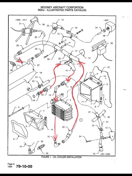
-
Thanks for your input. That’s what I was thinking too. And I saw reference to that method recently as well, perhaps on Beechtalk. But it appears that the factory Mooney installation was opposite of that, but I’m not 100% certain. Lycoming confirmed the actual flow direction for me this morning but said that proper flow through the cooler was determined by its manufacturer. Aero-Classic Coolers said air entrapment was no issue in any configuration (up, dowm, or sideways). I just want to confirm that Mooney directed the flow from top to bottom (for whatever reason). CNoe
-
A pleasure as well, as always. I indeed just posted my own inquiry on the Modern Mooney section. No big problem, in fact I just got out of Annual a week ago and am doing well. Hope the same for you and all!
-
Many of you are like me and have hundreds, if not thousands of pictures of their plane, both inside and out. So if anybody has a picture of the back of their engine showing how their Oil Cooler Hoses are connected and routed I would be most appreciative. To elaborate... I plan to replace my oil cooler and hoses soon and have found a possible discrepancy in my existing installation setup. Because of this I would like to confirm with at least 2 other J owners their hose connection/routing. I have referenced the Mooney Parts and Service Manuals and though it's not explicitly clear it does appear that one hose runs from the engine port just above/adjacent-to the Vernatherm to the lower (bottom) port of the oil cooler, while the other hose runs from the engine port near the middle of the accessory case to the upper (top) port of the oil cooler. In my J these connections are reversed with the first hose described above running to the upper oil cooler port. I assume that the previous engine installer made their own hoses during installation and did not follow the original hose routing/connections. I have spoken with both Lycoming Technical Services and Aero-Classics Oil Coolers about the proper connection order and the concensus is that it's "okay" in this application for the oil to flow either UP through the cooler or DOWN through the cooler but I'd like to employ the original factory routing. While I had read and was under the impression that the "correct" flow would pump the oil IN to the lower port and OUT the upper port this is apparently opposite of what I believe to be the original Mooney installation. So, if anybody can chime in with comments, or better yet a picture, I'd love to see how your J's cooler hoses are set up. For reference I will attach a pic of my current routing below. Note the two orange fire-sleeved hoses and compare to yours. Thank you, CNoe
.thumb.JPG.183480c6b4b8f2769ddd21159d6f1fd7.JPG)
-
Hi guys! True, I'm not on MS that often these days but I'm looking for help myself on another issue (may post a question shortly) and saw this inquiry. So in order to earn my keep I'll attempt to help you out... As I recall it's a pretty straight-forward process to tweak the potentiometer and eliminate the false alarms. For best results I'd recommend using a variable DC power supply such as this $60 unit on Amazon. https://www.amazon.com/RoMech-30V-Power-Supply-Variable/dp/B081SFKW2R/ref=sr_1_5?dchild=1&keywords=30V%2BDC%2Bpower%2Bsupply&qid=1600368169&sr=8-5&th=1 You can also use this power supply to exercise and evaluate your old autopilot servos and other such fun stuff! Remove the annunciator unit from the panel and open up the box to expose the PCB. The correct pot to adjust is shown in the middle of the attached pic; it's the one with the red blob of sealant on it. With the power supply preset at perhaps 10V and a nominal amperage (1A?) turn the power supply "OFF". Then connect the positive lead of the power supply to the appropriate connector pin on the bottom of the PCB and the power supply's ground lead to the PCB's ground pin. I don't remember exactly which pin numbers these are so if you don't know and don't have the schematic let me know and I'll try to find that info. From there you turn the power supply "ON" and confirm an output of <12V and confirm that the "LOW VOLTAGE" annunciation light is ON. Now slowly increase the voltage output until the "LOW VOLTAGE" annunciation light goes OFF and note the voltage (I wouldn't go any higher than 14.5V or so out of caution). NOTE: The previous step is just to give you an idea how far out of adjustment it is and isn't critical or even necessary. To make the adjustment set your voltage back to ~12.5V output on the power supply and then use a small screwdrived to break the potentiometer's adjustment screw loose and turn left or right until the annunciation light just extinguishes. After making the adjustment fine tune things by again reducing the power supply output voltage from ~14V very slowly until the annunciation light comes on (note the output voltage at that point). Make minor adjustments until the light comes on when voltage is at 12.5V. Once you've got it set put a little dab of torque-seal or fingernail polish on the pot to keep it from vibrating back out of adjustment. That's pretty much all there is to it. Feel free to inquire further if needed. CNoe
.thumb.JPG.4af0dd5d9f32166291aa0619969bf102.JPG)
-
Hey! I missed you at Oshkosh this year. But then I missed EVERYBODY at Oshkosh this year. CNoe
-
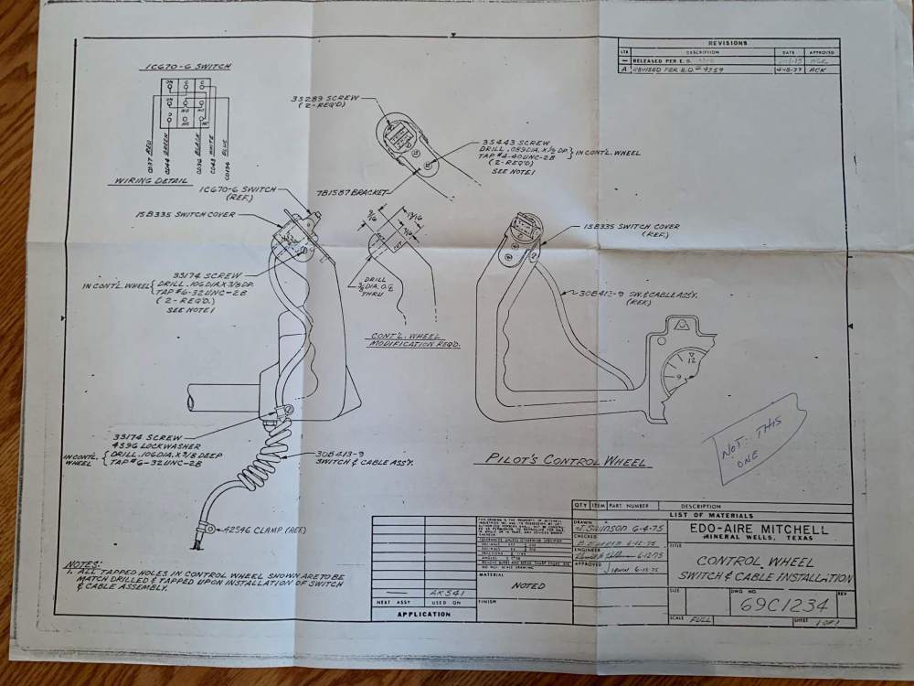
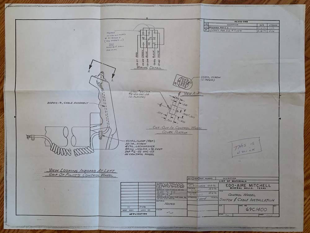
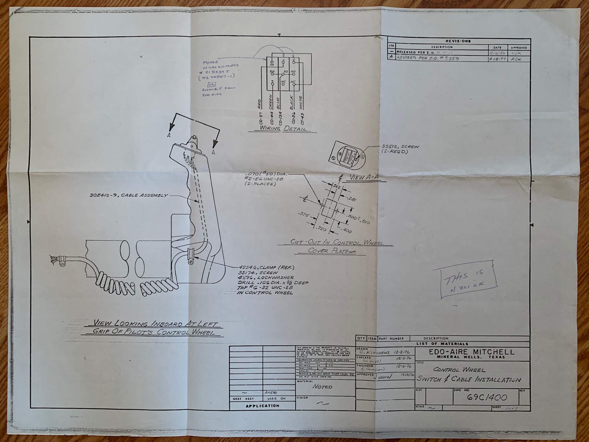
NicoN, We all make mistakes; I won't mention mine here. Do you believe that nothing shorted out and that the wires were simply ripped loose (master switch was OFF)? I've got a couple of different drawings/schematics from the factory "Edo-Aire Mitchell" trim-switch installations that I'll attach as a .jpg. It's been a while since I messed with that system, and on my installation I do not have "auto-trim". The trim servo is independent of the "altitude hold" system and does not utilize a "clutch". My "altitude hold" system (STEC) was a later addition that only annunciates an out-of-trim situation; the pilot must trim manually (either electric or with the trim-wheel). The independent trim-servo should be activated by applying 12V across the motor (and reverses with polarity change). But if you're tied into an A/H unit it could be different. I also believe (but am not certain) that there is a box behind the panel containing a relay for the electric-trim system that isolates the micro-switches from the full amperage draw of the motor. You may hear a faint "click" of the relay under the panel as you compress the trim button. I don't have a diagram of that relay box. I hope this helps. Let me know if you have any other questions. CNoe
-
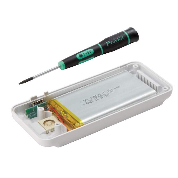
I dug up an old picture of my unsuccessful battery replacement attempt from 2016 to illustrate the type of battery that was previously employed. Note that the battery is glued into the housing and any attempt to remove it will likely tear the outer metallic pouch. As I recall it was 2 flat packs glued together and hard-wired in parallel to a small separate pcb. The soldering isn't a big deal but I couldn't source them at the time. Now they sell the entire assembly (half the Stratus) which makes replacement simple. The battery is now identifiable on pics of the Stratus kit as 3.7V 5400 mAh but I only find them on Chinese sites with high minimum purchase quantities. If anybody knows a good source for these domestically please let me know.
.thumb.JPG.50d4de06727998d41ea9ca1ce9f3a397.JPG)
-
Can you provide a link or good search term. I've searched on YouTube and am now quite proficient at changing the battery in a DODGE Stratus but can't seem to find anything about an Appareo Stratus. I'm obviously not putting in the correct search terms. Thanks!
-
My Stratus 2S has lost significant battery life as well, but not unreasonably I believe. I contacted Appareo support about this last September noting that I'd conducted 259 flights/335 logged hours using the device and was getting about 6+ hours out of the battery (new rated life is 8 hours). I've logged another ~57 hours since then and it seems to last about 4.5-5 hours now so it's definitely declining more quickly. In the past Appareo didn't offer do-it-yourself battery replacements and I learned with my original Stratus 2 that the battery was a proprietary flat-pack which I basically destroyed during disassembly. They were gracious enough to take my old unit (Stratus 2 that I screwed up) and replace it with a newer 2S unit for only $200 which I considered quite fair. In recent discussions with them regarding my declining battery they stated - "Based on the stats you provided about the battery, it is pretty average. Depending on the charging cycles, care of the unit, storage techniques, etc., we see batteries start to deplete around the 2.5-3 year mark or about 300 hours. There is a gauge associated with the battery that may develop a "memory" and performing a factory reset will help with this. If you haven't done so, please perform a factory reset on your unit, charge it fully, run down the battery, and then charge it back up again. This should reset this gauge." Regarding the Sentry unit you lose the ability to connect an external ADS-B or GPS antenna which is a deal-breaker for me. I keep my Stratus under the pilot's seat and use both external antennas (which also provide GREAT reception, even down low). This also keeps the unit out of the sun which should help battery life as well. I have a permanent USB power port on my panel and will plug in the Stratus on flights of 4+ hours but will likely be purchasing the battery replacement kit soon as it continues to decline.
-
Upfront notice: I am a long-time user and fan of Foreflight. But... I’m mildly interested in the new feature “Airport 3D View” and have contacted Foreflight support about making it available as an add-on or ala-carte feature. It’s simply not worth an additional $100 (Performance Plus subscription) but I’d be willing to pay another $20-$25 to try it out for a year. Their reply offered some hope (that they may offer it as an add-on in the future) but for now they’re trying to entice people to upgrade to the higher subscription. If they get significant interest in making it an add-on that might help so if you're interested please drop them a note. The e-mail to inquire is team@foreflight.com The partial text of my e-mail and their reply was as follows: Inquiry: “With the introduction of your new feature “Airport 3D View” I thought it might be worth checking out but was disappointed that it’s only available as part of your Performance Plus subscription (which is overkill for my needs). I do realize that you’re offering a special on that subscription as an inducement, but Pro Plus is a much better fit for me. So… I thought I’d check to see if the new feature might be available as an add-on. In the past your website offered a “Build Your Own Plan” option at the bottom of the pricing page but that seems to have been discontinued. I was sorry to discover that, because I might be willing to add the “Airport 3D View” option as a $20-$25 subscription add-on. I simply can’t justify another $100 for that one feature.” Reply: Tom here - Thanks for your feedback. We try to offer a variety of features at different price points to accommodate different budgets. We often add new features to existing subscription levels for free. For example, Breadcrumbs was added for free to all subscription levels with ForeFlight 11 at no additional cost. Some new features are deemed to be premium features and are only available with a higher priced subscription. It is possible 3D maps may be included as an "ala-carte" feature in the future, but at this time, it is only available with Performance Plus.
-
@jetdriven has a good memory of what’s in my hangar. Let me know if you need a replacement cover. I have some extras indeed and you’ve helped me out in the past. They have nutplates; no need for rivets. None on my J are riveted.
-
Byron pinged me and said y'all were looking for this... Cnoe McCauley S.L. 1998-22A.pdf
-
Stratus external GPS antenna satellite interference follow-up.
cnoe replied to cnoe's topic in Avionics/Panel Discussion
My issue was with the external "GPS" antenna, not the ADS-B antenna. I replaced the Stratus (GPS) antenna with Garmin's GA-25MCX and haven't had any problems since. Sorry I can't give you any help with your project. -
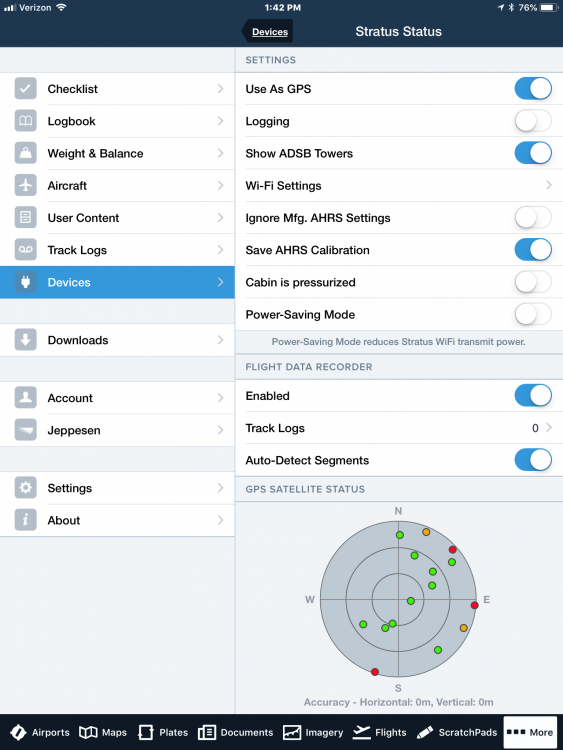
Back in 2014 @JohnB started an excellent post regarding interference issues caused by a failing (external) GPS antenna on his Stratus ADS-B receiver. Specifically a failing external (active) GPS antenna can suddenly cause your CERTIFIED GPS devices to lose satellite reception. The problem can be intermittent or last for considerable periods of time. Experiencing such a failure while on a direct-to route in IMC can be a real nuisance requiring notification to ATC and conversion to alternate methods of navigation. This issue has since been explored more fully (on MS, BT, and elsewhere) and the quick fix while enroute is to simply unplug the external antenna which should restore your panel GPS' functionality. This may or may not be a simple thing to do if your unit isn't readily available in the cockpit (under a seat or on a hat-rack). The folks at Appareo (the maker of Stratus units) have now admitted the existence of the issue and it is noted in their User Manual which states... "WARNING: Avoid pinching or bending the external GPS cable, especially near the antenna. This could damage the cable and cause interference between the antenna and other on-board GPS receivers. The cable’s minimum bend radius is 1 inch." As an avid user of the Stratus units I prefer to place it beneath the pilot seat (out of the sun and out of the way) and I employ both external ADS-B and GPS antennas which provide outstanding reception/coverage. Then I too experienced unexplained simultaneous GPS outages in my certified Garmin navigation equipment (as well as every other GPS receiver in the plane including the iPad and iPhone). At the time I was unaware of the issue described. Thanks to Mr. B and others I was able to discover the issue with some online sleuthing prior to spending large sums of money at the A&P/Avionics shops. So, when I decided to replace my existing (failing) antenna I wanted to look for an alternate, perhaps more robust antenna and began looking at options. As it turns out there are several antenna manufacturers out there with comparable products. The connector is a standard MCX version and I'd always been unhappy with the routing of the stock Stratus (actually AntennaFactor/LinxTechnologies) antenna which employed a straight-out cable. So after some studying and perusing I came to believe that the Garmin GA-25MCX antenna would be a suitable replacement (at half the cost for you CB'ers), and to make matters even better the connector employs a 90 degree fitting which permits much better cable routing in my case. So I bought one to try and am making this post to confirm that it works just fine so far. I've yet to complete in-flight testing with it but in ground testing I found it to pick up a full compliment of satellites without issue (see photo). Let me end by stating that I will monitor it for interference issues and if any arise I will report them here, but it is my understanding that the issue only occurs when the antenna is experiencing a failure of some sort, which mine was. I hope this helps somebody, as Mr. B's post helped me.
- 8 replies
-
- 2
-

-
- gps signal loss
- stratus
- (and 3 more)
-
Mixture cable does not look right?
cnoe replied to Gary0747's topic in Vintage Mooneys (pre-J models)
That happens when the end rod gets bent slightly. It binds inside the other tube and when you push the mixture knob forward it pops the joint apart. It can be repaired by carefully straightening the rod then reinserting the tube into its socket. I’ve seen the safety wire trick but if it’s binding it will just pop out again. If you get it working well again use a short piece of heavy duty shrink sleeve (the kind with meltable adhesive sealant inside) to keep the joint both secure and sealed from the elements. Sent from my iPad using Tapatalk -
If you change your mind here’s the place I’ve heard good things about. http://www.mirrorfinishpolishing.com/ I can’t recall what they quoted me as it’s been a few years back. Before and after pics from their website: Sent from my iPad using Tapatalk
-
There are companies that can do this; it’s been discussed a lot in the past. It’s not really something you can do yourself economically. We’re not talking about an hour with Flitz and a buffer. Mine went from this... ...to this... ... but it involved selling the original and buying the shiny one from someone upgrading to a 3-blade. Sent from my iPad using Tapatalk
-
With all due respect to Jose’s fine modification I personally have no need for it. I can fly 990 nm for 6.6 hours (+ VFR reserve) with my stock tanks which is well beyond my personal limits. IMO every Monroy LR tank installation should include a free Monroy relief assembly (along with a free belly-washing contract).[emoji846] But until there’s female-friendly and dog-friendly options I’ll have to keep limiting my flights to 990 nm or less. Sent from my iPad using Tapatalk
-
Excellent air safety institute video with Mooney shoutout
cnoe replied to bradp's topic in General Mooney Talk
I agree that the ultimate answer is situational but also agree with the interviewee that once the fan up front stops making power the goal is to use the airframe as a vehicle to minimize energy transfer to its occupants. The tubular steel framed cabin is perhaps the #1 Mooney attribute. As the old adage goes “if the engine quits it’s the insurance company’s plane”. Having made a few landings on grass strips I can testify that our gear isn’t very compliant on rough ground so it would have to appear quite smooth before I’d leave it down. And remember how robust our birds are when bellied in. When’s the last time you heard of a Mooney being scrapped following a gear-up landing? Therefore my default is likely to keep the gear up during an off-field and only drop it if a decent roll-out looks likely. Sent from my iPad using Tapatalk -
https://skybolt.com/ You can get about anything you need there. Interchangeable with Camloks, and price competitive. Note that there are sometimes different lengths in different spots on the cowling. And if holes are worn you may want/need to adjust some lengths.
-
As others have mentioned I respectfully believe he is mistaken. If we were talking about the CHT gauge I would agree because it is specified as a requirement in the CAR 3 documents; that has been an issue for all of us that have JPI 700-800 series. We have to retain the original CHT gauge because it is required, primary, and those JPI models are NOT certified as primary instruments. Our planes were certified under CAR 3, not Part 23. That is also stated in the TCDS. That is what controls what is required in our planes. Try this link for the CAR 3 regs: http://www.navioneer.org/riprelay/Yet%20More%20Navion%20Files/car_part3.pdf The applicable page is attached as a screenshot. Edited: Sorry another bad link, due to Tapatalk I suppose. You can google it; the navioneer site has a copy. Here’s what you’re looking for. Sent from my iPad using Tapatalk
-
It looks like the link to your TCDS was bad so here you go again: http://rgl.faa.gov/Regulatory_and_Guidance_Library/rgMakeModel.nsf/0/6ee01384f2e646e986258100005b0b61/$FILE/2A3_Rev57.pdf Read page 30 carefully; the EGT gauge is not mentioned. It states that required equipment is spelled out in the CAR 3 standards which says you must have a CHT gauge but no EGT gauge. It’s therefore not required. Also, our Part 91 Mooneys don’t have a “minimum equipment list” either. Edited: Link still bad... try going here then doing a make/model search. http://rgl.faa.gov/Regulatory_and_Guidance_Library/rgMakeModel.nsf/Frameset?OpenPage Sent from my iPad using Tapatalk


.JPG.3a1cdf1bbeb918b06e444e0b977a6ef8.JPG)
.JPG.4170581fdca324cdac4ed3878502491a.JPG)


.JPG.3e243b79d0806e69b84168f42e757aaf.JPG)

